
Related Manuals for Severn Trent NXT3000

Summary of Contents for Severn Trent NXT3000
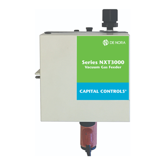
- Page 1 Instruction Bulletin - Series High Capacity NXT3000 Wall Mounted Vacuum Regulator 1,000 - 3,000 PPD (30-60 Kg/h) Maximum - 1 - 105.6605.0...
- Page 2 Severn Trent Water Purifi cation, Inc. cannot be responsible for the overall system design of which our equipment may be an integral part of or any unauthorized modifi cations to the equipment made by any party other that Severn Trent Water Purifi...
-
Page 3: Table Of Contents
Table of Contents INTRODUCTION ............... . . 4 General . -
Page 4: Introduction
See Bulletin 005.9001 for Severn Trent Services equipment warranty. NOTE: The High Capacity NXT3000 vacuum regulator is designed for use in systems where the feed rate is manually or automatically set and operation is either continuous or start/stop. The Severn Trent Services equipment warranty and service policy is null and void, as it pertains to user pro tec tion, if the High Capacity NXT3000 Series vacuum regulator is misapplied. -
Page 5: Specifi Cations
Specifi cations Capacity: Chlorine - 1000 to 3000 PPD (20 kg/h to 60 kg/h) Sulfur Dioxide - 1000 to 2000 PPD (20 kg/h to 40 kg/h) Ammonia - 500 to 1000 PPD (10 kg/h to 20 k/gh) Carbon Dioxide* - 750 to 1500 PPD (15 kg/h to 30 k/gh) *Due to the high gas pressure in the carbon dioxide storage cylinders, a two stage pressure regulator is required between the gas source and the vacuum regulator. -
Page 6: Operation
OPERATION General A. Vacuum Regulator The vacuum regulator serves to reduce the gas supply pressure to a regulated vacuum for safe transport of the gas to the point of application. A leak in any portion of the vacuum transport line simply allows air to be pulled into the system. -
Page 7: Principles Of Operation
The manifold assembly has a liquid chemical trap, a wrap-around type heater and a cartridge type fi lter. The trap catches any condensed gas vapors (liquid chemical) which may form in the gas supply line to prevent its entrance into the regulator. The heater vaporizes any liquid chemical and prevents any gas from condensing in the manifold, thereby permitting only gas to enter the regulator. -
Page 8: Basic System Schematics
Automatic Change-Over Single Regulator System Dual Regulator System Manual Control Manual Control Automatic Change-Over Single Regulator System Dual Regulator System Automatic Control Automatic Control Figure 1 - Basic System Schematics 105.6605.0 - 8 -... -
Page 9: Installation
INSTALLATION Select a location which can be isolated from unauthorized personnel. Outdoor installations for wall mounted regulators are not recommended (especially if the gas supply system consists of two or more containers) since a sudden decrease in ambient temperature will result in the formation of condensed gas vapors (liquid chemical) in the gas supply line. - Page 10 105.6605.0 - 10 -...
- Page 11 GENERAL One of the gas inlet connections is fi tted with a plug. The plug can be removed and installed in the opposite side if it is not convenient (when mounting on a wall) or possible (when mounting on the gas valve of a ton container) to use the open connection as supplied.
-
Page 12: Connections - Wall Mounted Vacuum Regulators
NOTE: USE ONLY APPROVED TYPE FLEXIBLE CONNECTORS AND ADAPTOR FITTINGS, AS RE QUIRED, IN THE CONSTRUCTION AND IN- TERCONNECTION OF ALL FLEXIBLE PIPE RUN PORTIONS OF THE GAS SUPPLY SYSTEM PROCEDURE FOR CONNECTION TO THE GAS SUPPLY SYSTEM 1. The manifold is provided with an appropriate adaptor For three or more container systems the manifold is fi... -
Page 13: Out-Of-Gas Alarm Switch
An optional, fi eld mountable, switch is available for remote indication of a loss of gas supply. The switch may be at tached directly to the vacuum regulator body without disassembling the body. Refer to Instruction Bulle- tin100.6703 and parts list 100.7603 for further details. The kit P/N is 674B093U02 Figure 5 - Out-of-Gas Alarm Switch - 13 - 105.6605.0... -
Page 14: Wall Mounted Vacuum Switches
Accessories: Wall Mounted Vacuum Switches Legend: Inches [millimeters] Figure 6 - Wall Mounted Vacuum Switches Wall mounted Nema 4X vacuum switches are available for remote indication of out of spec vacuum conditions. Low vacuum only (loss of ejector operation, break in vacuum line), P/N 806L051U02. High vacuum only (out of gas, gas source valve closed), P/N 806L051U06. -
Page 15: Vacuum Regulator Exploded View
See parts list 100.7609 for part number details Figure 7 - Vacuum Regulator Exploded View - 15 - 105.6605.0... -
Page 16: Operating Instructions
OPERATING INSTRUCTIONS Initial Start-Up Prior to start-up after an extended shutdown, inspect all lines and con nec tions, making replacements as neces- sary. If lines are transparent, inspect for blockage. Disconnect any blocked line and clean by blowing down. If lines cannot be visually in spect ed, disconnect the lines and blow down to make certain no block age exists. - Page 17 B. Checking for Gas Leaks 1. General The test solution to be used in each of the following procedures is dependent upon the gas being handled. Use a 26°Baume' (ammonium hydroxide, aqua ammonia) ammonia solution for chlorine and sulfur dioxide systems and a 10% hydrochloric (muriatic) acid solution for ammonia systems. NOTE: Household ammonia is not strong enough to serve as a test solution.
- Page 18 d. Turn on the water supply to the ejector and open the isolating valve or header valve (NOT THE CONTAINER VALVE) that was left closed in paragraph c) above. e. Open the rate valve on the chlorinator and observe the rotameter. There will be an immediate indication of fl...
-
Page 19: Operation
WARNING Using ton containers as the gas source requires additional care at start-up time, as liquefi ed gas will be present in the container gas eduction tube. Slowly open the container gas valve and stop when a cavitation noise is heard. This is the liquefi... - Page 20 CAUTION The rate valve is not designed to serve as a shut-off valve. Attempting to use it in this fashion may result in valve damage. Refer to Instruction Bulletin 010.3650 for information pertaining to care of ton containers and maintenance of gas tight seals at all coupling (and fl ange, if applicable) type connections. Refer to the troubleshooting chart (troubles “E”...
- Page 21 CAUTION Maintaining ejector operation with the fl exible connectors removed from the exhausted cylinder(s) will allow moist atmospheric air to be drawn into the gas feed system. This moisture in the presence of chlorine or sulfur dioxide gas will result in the production of acids which will deteriorate the equipment.
- Page 22 WARNING If the “status” lever cannot be moved to its reserve position, this indicates that the supply of gas for the other regulator has been exhausted. If this is the case, close the cylinder or container valve associated with the gas supply system of the other regulator. Then, shut off the water supply to the ejector(s).
-
Page 23: Shutdown
SHUTDOWN Shutdown For Servicing 1a. If the gas dispensing system is of the single regulator type, close each cylinder and/or container valve associated with its gas supply system. 1b. If the gas dispensing system is of the dual regulator type, close each cylinder and/or container valve associated with the gas supply system of both regulators. -
Page 24: General
When a part needs replacing, it is mandatory that the new part needs to be made of materials that will withstand the corrosive action of the gas being handled. Failure to use proper replacement parts as supplied by Severn Trent Services can result in bodily injury. 105.6605.0 - 24 -... -
Page 25: Cleaning Agents
If desired, the equipment in need of repair may be returned to Severn Trent Services , 3000 Advance Lane, Colmar, PA 18915 for servicing or complete overhaul. -
Page 26: Troubleshooting Chart
TROUBLESHOOTING CHART TROUBLE PROBABLE CAUSE CORRECTIVE ACTION 1. Flowmeter fails to indicate a. Length of vacuum line(s) a. Refer to bulletin 100.4601 & required air fl ow rate when exceeds maximum allowable 121.3003 operating vacuum is being transport distance. checked the fi rst time that the Gas Dispensing System is placed b. - Page 27 TROUBLE PROBABLE CAUSE CORRECTIVE ACTION 4. Flowmeter continues to indicate air a. Leakage around seal plug O-ring a. Tighten seal plug; or inspect and fl ow and/or "status" lever of in auxiliary connection of reset or renew O-ring, as required. regulator fails to move to its fl...
- Page 28 TROUBLE PROBABLE CAUSE CORRECTIVE ACTION 9. "Status" lever of regulator moves to a. Gas supply valve(s) inadvertently a. Open all supply valve(s) to a total of its EMPTY position during the course closed. one full turn. of normal operation. b. Gas supply exhausted. b.
- Page 29 - 29 - 105.6605.0...
- Page 30 Design improvements may be made without notice. Represented by: Severn Trent Services 3000 Advance Lane Colmar, PA 18915 Tel: 215-997-4000 • Fax: 215-997-4062 Web: www.severntrentservices.com E-mail: marketing@severntrentservices.com Copyright 2007 Severn Trent Services 07/07 105.6605.0 - 30 -...
Need help?
Do you have a question about the NXT3000 and is the answer not in the manual?
Questions and answers