
Related Manuals for CORNING LANscape TKT-UNICAM-PFC

Summary of Contents for CORNING LANscape TKT-UNICAM-PFC
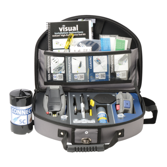
- Page 1 Installation Guide for the TKT-UNICAM-PFC Tool Kit with FBC-007 Cleaver www.corning.com/cablesystems/unicam US and Canada: 1-800-743-2671 International: +1-828-901-5000 006-394 Issue 1...
- Page 2 Corning Cable Systems reserves the right to improve, enhance, and modify the Corning Cable Systems LLC features and specifications of Corning Cable Systems’ products without prior notification. UniCam is a registered trademark of Corning Cable Systems PO Box 489 Brands, Inc. ST is a registered trademark of Lucent Technologies. All other Hickory, NC 28603-0489 USA trademarks are the properties of their respective owners.
-
Page 3: Table Of Contents
tKt-unICaM-PfC t 006-394 I nstallatIon uIde for the ssue Table of Contents Introduction . . . . . . . . . . . . . . . . . . . . . . . . . . . . . . . . . . . . . . . . . . . . . . . . . . . . . . . . . . . . . . . . . . . . . . . .v Safety Precautions . - Page 4 Fiber Cleaving with FBC-007 Cleaver . . . . . . . . . . . . . . . . . . . . . . . . . . . . . . . . . . . . . . . . . . . . 21 5 .1 .
-
Page 5: Introduction
Fiber stub TPA-2593 Mechanical splice with index matching gel ST Compatible Please become familiar with the entire manual before starting to assemble a connector . Visit www .corning .com/cablesystems/unicam for more information and videos showing this procedure . ntroduCtIon... - Page 6 ntroduCtIon THIS PAGE INTENTIONALLY LEFT BLANK . tKt-unICaM-PfC t 006-394 I nstallatIon uIde for the ssue...
-
Page 7: Safety Precautions
tKt-unICaM-PfC t 006-394 I nstallatIon uIde for the ssue Safety Precautions Optical Fiber Precautions WARNING: Cleaved or broken glass fibers are very sharp and can pierce the skin or damage the eyes easily. Do not let pieces of fiber stick to your clothing or drop in the work area where protect your eyes. Use tweezers to pick up pieces of fiber and place them on a loop of tape kept for that purpose alone. - Page 8 . Doing so may cause damage that can alter the transmission characteristics of the cable; the cable may have to be replaced . For additional safety information, please visit www .corning .com/cablesystems/safety . tKt-unICaM-PfC t...
-
Page 9: Getting Started
. TPA-2758 1.2. High-Performance UniCam Tool Kit Contents ® ST Compatible Table 1 describes the contents of the Corning Cable Systems High-Performance UniCam Tool Kit . ® Number Item Part Number UniCam Tool Kit Trash Container... -
Page 10: Compatible Connectors And Ordering Information
NOTE: To order an organizer pack containing 25 connectors, add –Z to desired part number above (e.g., 95-000-50-Z) Keyed LC solutions are also available . Visit www .corning .com/cablesystems and enter “LAN-701-EN” into the search engine for detailed information . - Page 11 tKt-unICaM-PfC t 006-394 I nstallatIon uIde for the ssue 1.3.1 Components Each UniCam connector package contains the parts shown in this section of the manual . ® SC Connector 900 Micron Boot Lead-in Tube Ferrule Crimp Dust Ring 2.9 mm Boot Rear Dust Shroud 2.9 mm Boot...
- Page 12 ettInG tarted THIS PAGE INTENTIONALLY LEFT BLANK . tKt-unICaM-PfC t 006-394 I nstallatIon uIde for the ssue...
-
Page 13: Overview Of Installation Tools
tKt-unICaM-PfC t 006-394 I nstallatIon uIde for the ssue 2. OVERVIEW OF INSTALLATION TOOLS This chapter provides an overview of the tools required for installing SC, LC, and ST Compatible UniCam connectors . ® ® 2.1. High-Performance UniCam Installation Tool 2.1.1 General This section describes the components of the High-Performance UniCam Installation Tool . - Page 14 nstallatIon ools 2.1.2 Features and Components Number Components Cover VFL Coupler Power Switch Power Light Error Light Connector Cradle Photo Receptor Reset Button Red Light Green Light Crimp Knob Wrench CAM Button Laser Aperture 2 .50 mm Ferrule Adapter (ships in the tool) Ferrule Adapter Port LOAD Button Jumper...
-
Page 15: Fbc-007 Cleaver
tKt-unICaM-PfC t 006-394 I nstallatIon uIde for the ssue 2.2. FBC-007 Cleaver 2.2.1 General This section describes the components of the FBC-007 Cleaver . Please read through this entire chapter, the Fiber Preparation chapter, and Fiber Cleaving chapter before using the cleaver . Refer to Chapter 5 for complete operating instructions and precautions . - Page 16 nstallatIon ools THIS PAGE INTENTIONALLY LEFT BLANK . tKt-unICaM-PfC t 006-394 I nstallatIon uIde for the ssue...
-
Page 17: Tool And Connector Preparation
tKt-unICaM-PfC t 006-394 I nstallatIon uIde for the ssue 3. TOOL ANd CONNECTOR PREPARATION 3.1. Tool Preparation Tool is designed to be held in the left hand while working . 3.1.1 Open the Cover Step 1: Ensure the components are in the starting position. If not: •... -
Page 18: Connector Preparation
ool and onneCtor reParatIon 3.1.2 Switch Power On Step 1: Locate power switch and light in the upper left corner of the tool . Power Step 2: Move the switch to the ON position . Once the tool is on, the Power Light Light will glow . -
Page 19: Connector Loading
tKt-unICaM-PfC t 006-394 I nstallatIon uIde for the ssue 3.2.2 Prepare Connector for Loading Step 1: Remove the rear dust cap . Step 2: Remove the clear ferrule dust cap and visually inspect the connector for damage . Step 3: Leave the black load adapter on LC and ST Compatible connectors ®... - Page 20 ool and onneCtor reParatIon Step 2: With the connector oriented up (as shown on page 10), Crimp load the connector into the tool by inserting it, lead-in Arms tube first, into the Wrench. NOTE: Ensure that the cam is completely seated in the Wrench and the lead-in tube protrudes through the crimp arms.
- Page 21 tKt-unICaM-PfC t 006-394 I nstallatIon uIde for the ssue Step 4: Slide the VFL Coupler down until the Ferrule Adapter is seated on the connector . Step 5: Close the cover and check for the Error Light . • If the Error Light remains off, there are no problems . Proceed to “Section 4 . Fiber Preparation”...
- Page 22 ool and onneCtor reParatIon THIS PAGE INTENTIONALLY LEFT BLANK . tKt-unICaM-PfC t 006-394 I nstallatIon uIde for the ssue...
-
Page 23: Fiber Preparation
tKt-unICaM-PfC t 006-394 I nstallatIon uIde for the ssue 4. FIBER PREPARATION 4.1. All Fiber/Cable Types Slide the appropriate boot onto the fiber/cable. • Use the 900 micron boot for 900 micron Tight-buffered, 900 micron Furcated . • Use the 1 .6, 2 .0, or 2 .9 mm cable boot for Jacketed Cable applications . - Page 24 Iber reParatIon Step 2: To expose bare glass, remove the 40 mm section of buffer and coating in two steps using the Dual-Hole Miller Tool . • For the 900 micron buffer, use the large hole . • For the 250 micron coating, use the small hole . Large hole Small hole TPA-2785...
-
Page 25: Jacketed Cable
. Step 1: Measure and mark 40 mm and 53 mm points . TPA-2788 40 mm (1.5 in) 13 mm CORNING – SMF–2 TYPE OFNR – (UL) 01844 FEET TPA-2790 TPA-2789 NOTE:... - Page 26 Iber reParatIon Cable Jacket Diameter AWG Size Step 2: Refer to table for the correct AWG opening for the 1 .6 mm cable being used and strip off the 40 mm section of outer jacket with the Jacket Stripping Tool . 2 .0 mm 2 .9 mm KPA-0876...
- Page 27 tKt-unICaM-PfC t 006-394 I nstallatIon uIde for the ssue 2nd Mark SC or ST Compatible Step 7: Use the Dual-Hole Miller Tool to remove the 40 mm of buffer 2nd Mark LC and coating in two steps: (same as step 3 from section 4.3). 40 mm of 125 micron fiber NOTE: It is IMPORTANT to check the locations of the...
-
Page 28: 900 Micron Fan-Out Tubing Applications
Iber reParatIon 4.4. 900 micron Fan-out Tubing Applications Step 1: Remove the 900 micron tubing with Dual-Hole 4 mm Miller Tool or trim back the fiber so that 44 mm of fiber protrudes from the 900 micron tubing. 900 micron Step 2: Measure and mark the 250 micron coated fiber tubing 44 mm of... -
Page 29: Fiber Cleaving With Fbc-007 Cleaver
tKt-unICaM-PfC t 006-394 I nstallatIon uIde for the ssue 5. FIBER CLEAVING WITH FBC-007 CLEAVER 5.1. Cleaving 900 Micron Fiber Step 1: Depress Black and Red buttons . Step 2: Insert fiber until it stops. TPA-3715 TPA-3714 Step 3: Gently release buttons . Step 4: Cycle Red button once . - Page 30 Iber leavInG Step 5: Gently press Blue button . Step 6: Hold fiber and press Black button to remove. TPA-3718 TPA-3719 Step 7: Check cleave length against guide . Step 8: Hold scrap fiber and press Red button to remove . TPA-3717 TPA-3713 tKt-unICaM-PfC t...
-
Page 31: Cleaving Jacketed Fiber
tKt-unICaM-PfC t 006-394 I nstallatIon uIde for the ssue 5.2. Cleaving Jacketed Fiber Step 1: Flip fiber handler. Step 2: Follow Steps 1 through 8 for cleaving 900 micron fiber. TPA-3720 5.3. Cleaving UniCam Fanout Applications ® Step 1: Add handler track to cleaver . Remove 900/2 .9 handler . - Page 32 Iber leavInG Insert handler track . Depress latch while pressing cover firmly to close . Press Latch TPA-3724 TPA-3723 Step 2: Strip fiber and check length against guide. Step 3: Load fiber into Blue UniCam fanout handler. OptiSnap 900 Micron Application (Blue Handler) Align coating to nose.
- Page 33 tKt-unICaM-PfC t 006-394 I nstallatIon uIde for the ssue Step 5: Cycle Red button once . Step 4: Depress Red and Black buttons and load handler with fiber into cleaver. TPA-3729 TPA-3728 Step 6: Press Blue button . Step 7: Press Black button and slide handler out of the cleaver .
- Page 34 Iber leavInG Step 8: Remove fiber from handler and check Step 9: Hold scrap fiber and press Red button to remove. cleave length against guide . TPA-3732 TPA-3725 tKt-unICaM-PfC t 006-394 I nstallatIon uIde for the ssue...
-
Page 35: Connector Termination
tKt-unICaM-PfC t 006-394 I nstallatIon uIde for the ssue 6. CONNECTOR TERMINATION 6.1. Termination Process NOTE: THE COVER MUST BE CLOSED FOR THE SYSTEM TO FUNCTION . Step 1: Insert a cleaved fiber into the back of the lead-in tube. Insert the fiber until you feel it firmly stop against the fiber stub. - Page 36 onneCtor erMInatIon Step 3: Check the termination lights . • If the green light is illuminated, the termination was successful . Proceed to Step 4 . NOTE: The green light ensures proper termination of the connector . However, it is not a substitute for system testing .
- Page 37 tKt-unICaM-PfC t 006-394 I nstallatIon uIde for the ssue Step 4: Release fiber and turn the Crimp Knob 180 degrees in either direction. • There may be slight resistance while turning the knob; this is normal . • Turning the Crimp Knob crimps the lead-in tube onto the fiber, thus locking the connector to the fiber.
-
Page 38: Completing The Connector Assembly
onneCtor erMInatIon 6.2. Completing the Connector Assembly Complete the connector assembly process by following the appropriate steps below for your connector type . NOTE: If not using on Jacketed Cables skip Section 6 .2 .1 and proceed to the section for your connector type . 6.2.1 Jacketed Cables Step 1: Ensure the ferrule dust cap is installed . - Page 39 tKt-unICaM-PfC t 006-394 I nstallatIon uIde for the ssue Step 5: Place the connector crimp ring into the opening of the crimp tool jaws . Step 6: Squeeze the handles shut until they automatically release, indicating completion of the crimp . Remove the connector and cable from the tool .
- Page 40 onneCtor erMInatIon 6.2.3 LC Connectors Step 1: Ensure the clear ferrule dust cap is installed . Step 2: Remove the black load adapter . Step 3: Slide the trigger up to the back of the connector and latch its arms into the windows of the housing . Step 4: While holding the connector by the front dust cap, slide the correct strain-relief boot up the back of TPA-2649...
-
Page 41: Maintenance And Troubleshooting
tKt-unICaM-PfC t 006-394 I nstallatIon uIde for the ssue 7. MAINTENANCE AND TROUBLESHOOTING This section provides maintenance and troubleshooting information for the High-Performance Installation Tool, FBC-015 Cleaver, and UniCam connectors . ® 7.1. High-Performance Installation Tool 7.1.1 Changing the Batteries Step 1: Verify the tool is turned off . - Page 42 aIntenanCe and roubleshootInG Step 2: Insert the stick into the adapter opening and rotate the tip clockwise 10 revolutions . Step 3: Apply varying pressures to create a gentle pumping action . Step 4: Dispose of each cleaning stick after use . Do not use sticks more than once .
- Page 43 tKt-unICaM-PfC t 006-394 I nstallatIon uIde for the ssue Step 4: Install the new Ferrule Adapter onto the Ferrule Adapter Port in the VFL Coupler . Step 5: Be sure the key on the Ferrule Adapter is aligned with the keyway on the Ferrule Adapter Port, and then tighten firmly.
-
Page 44: Maintaining The Fbc-007 Cleaver
aIntenanCe and roubleshootInG 7.2. Maintaining the FBC-007 Cleaver 7.2.1 Opening Cleaver for Cleaning or Maintenance Depress latch and lift cover . Depress latch while pressing the cover firmly to close. Press Latch TPA-3716 TPA-3722 7.2.2 Cleaning Wipe three places with fiber wipes and cleaning fluid. -
Page 45: Connector Cleaning
KPA-1000 TPA-3734 7.3. Connector Cleaning Clean UniCam connectors with Fiber Wipes and Fiber Optic Cleaning Fluid. Corning Cable ® Systems recommends using this cleaning procedure every time a connector is unmated or the connector is excessively dirty . TPA-2817 aIntenanCe and... -
Page 46: Troubleshooting
aIntenanCe and roubleshootInG Step 1: Take a Fiber Wipe and fold once to make a square. Step 2: Place the wipe on saturator top of the Fiber Optic Cleaning Fluid and press two to three times to wet the wipe . Step 3: Wipe the connector end face with the wet wipe to remove dirt and debris. - Page 47 tKt-unICaM-PfC t 006-394 I nstallatIon uIde for the ssue Problem Possible Causes Solutions (Actions) Amber Error Light flashes 2 . Connector loaded incorrectly . 2 . Ensure the connector is loaded into the tool correctly . (continued) • The date code on SC, the LC latch, or the “UP” on the ST compatible load adapter must be up .
-
Page 48: Testing Unicam ® Connectors
5 . Bad cleave dur to debris in the clamps . 5 . Refer to the “Cleaver is producing bad cleaves . . .” troubleshooting problem above . If unable to successfully troubleshoot the installation tool using the table above, call Corning Cable Systems Technical Support at 1-800-743-2671 . 7.5.
Need help?
Do you have a question about the LANscape TKT-UNICAM-PFC and is the answer not in the manual?
Questions and answers