Table of Contents
Advertisement
Quick Links
Advertisement
Table of Contents

Related Manuals for DK-Audio MSD100 Series

Summary of Contents for DK-Audio MSD100 Series
- Page 2 MSD100 MSD100AES/MSD100AES-SA MSD100T/MSD100T-SA MSD150C MASTER STEREO DISPLAY USER’S MANUAL...
- Page 3 Devices, Inc. USA Crystal is a registered trademark of Crystal Semiconductor Corp., USA Note: This manual covers all MSD100 Series models. The main text refers to the MSD100 but applies to all models. Special notes, subsections and tables are provided to describe operational features that are unique...
-
Page 4: Table Of Contents
O N T E N T S 1. Introduction 1.1 Using This Manual ......... . 1-3 1.2 Notation Conventions . - Page 5 ONTENTS 4. Operation 4.1 Main Display and Control Keys ......4-1 4.1.1. Initial Display at Power Up......4-2 4.1.2 Function Keys.
- Page 6 ONTENTS Appendix A. Specifications A.1 Power Supply ..........A -1 A .2 Cabinet Dimensions .
- Page 7 ONTENTS List of Figures Figure 1-1 MSD Master Stereo Display ..... 1-1 Figure 2-1 MSD100 Dimensions ......2-3 Figure 2-2 RCA and XLR Connectors .
-
Page 8: 1 . I N T R O D U C T I O N
1 . I N T R O D U C T I O N This section provides a description of the MSD100 Series, lists related documentation and notation conventions, and provides product support contact information. The DK-Audio MSD100 Master Stereo Display Series models are universally recognized professional audio metering system for broadcast and studio applications. -
Page 9: Level Meter
The MSD100 Series models deliver monitoring capabilities beyond traditional instruments such as bar graphs, LEDs and oscilloscopes. All MSD100 Series units provide the following basic functions: • Phase Meter •... -
Page 10: Using This Manual
This manual contains information and instructions necessary to install, configure and operate the MSD100, MSD100AES, MSD100AES-SA, MSD100T, MSD100T-SA and MSD150C. It provides step-by-step instructions you must perform to install and operate your MSD100 Series model successfully. This manual contains the following information: Section 1 Introduction. -
Page 11: Notation Conventions
Registration Card. This page can be used if Registration the registration card is missing. Either the form or the card can be mailed or faxed to DK-Audio 1 . 2 N O T A T I O N O N V E N T I O N S Before you begin working with the MSD100, familiarize yourself with the notation conventions used in this manual. -
Page 12: Related Documentation
O C U M E N T A T I O N The following manuals provide additional information about related technologies and products, but are not required to install or operate the MSD100 Series. • MSD200/800 Series User’s Manual •... -
Page 13: Rma Request
N T R O D U C T I O N 1.4.1 RMA R EQUEST To return a DK-Audio or PTV product to us for repair or calibration/modification, you must submit a Return Merchandise Request (RMA) form. You can request to receive the RMA form as follows:... - Page 14 2 . 1 A U D I O E T E R I N G The DK-Audio MSD100 Master Stereo Display Series provides producers, sound engineers and technicians with an objective visual representation of audio characteristics. By supplementing the human ear with meters and scopes based on international standard measurement scales, the risk of over-reliance on subjective criteria is minimized.
-
Page 15: Overview
Studio and broadcast facilities • OB-Vans • Hard disc recording and editing systems • Home studios (MSD-100) The MSD100 Series provides serious audio professionals with these essential features backed by a 2-year warranty: • Phasemeter • Audio vector oscilloscope •... -
Page 16: Physical Overview
2 . 4 A U D I O N P U T S The rear-panel audio connection and signal types vary by model as described in Table 2-1. Table 2-1. MSD100 Series Rear Panel Connections Model Connector Type Signal type MSD100... -
Page 17: Power Supply
V E R V I E W 2 -2 . R C A ( L X L R ( R I G U R E E F T A N D I G H T O N N E C T O R S 2 . - Page 18 V E R V I E W 2 . 6 C O D E C I R C U I T The Codec circuit, included only on models MSD100, MSD100T, MSD100T-SA, and MSD150C, integrates key audio data conversion and control into a single IC. The Codec circuits include the following features: Anti-alias filter Low-pass filter used at the input of the ADC...
- Page 19 V E R V I E W Dynamic >80dB over 20kHz audio range range and signal-to- noise Sampling rate 48kHz, fixed 2 . 7 D E C O D E R ® The Crystal CS8412 decoder, installed on digital models MSD100AES and MSD100AES-SA, performs the following: •...
- Page 20 V E R V I E W The EPROM circuit is active only during program loading. All real-time computation is executed internally in the DSP. 2 . 1 0 L C D D I S P L A Y The dot-matrix Liquid Crystal Display (LCD) provides a graphic resolution of 320 dots (horizontal) by 240 dots (vertical).
- Page 21 V E R V I E W Digital AES/EBU inputs Digital AES/EBU outputs Link (loop through of dig. input) LED overload Audio connectors Phono ANALYSER Phasemeter Audio vector oscilloscope PPM/VU Level meter scales (plus DK-Scale PC program) Loudness (Leq(m)) Session log Statistical info mode FFT Spectrum Analyser 1/3 octave spectrum...
- Page 22 3 . I N S T A L L A T I O N This section describes how to mount the MSD100 and connect audio and power. 3 . 1 M O U N T I N G All MSD100 models are supplied with the following accessories for easy mounting on any console or desk: •...
- Page 23 N S T A L L A T I O N Insert star washers between the MSD100 and the bracket to ensure a firm grip. 3 -1 . M S D 1 0 0 M I G U R E O U N T E D I N R A C K E T 3.1.2 M...
- Page 24 N S T A L L A T I O N • Use standard audio signal cable or similar • Ensure that all connections are firmly secured • Allow sufficient loose cable for the unit to be tilted and turned Rear-cabinet connector types vary by model, as shown in Table 3-1.
- Page 25 N S T A L L A T I O N 3 -2 . F X L R M S D 1 0 0 T I G U R E E M A L E C O N N E C T I O N S 3 .
- Page 26 N S T A L L A T I O N 3 -2 . M S D 1 0 0 S A B L E U P P L Y V O L T A G E S P E C I F I C A T I O N S Operating range 9 to 20V AC, 50 Hz 9 to 30V DC...
- Page 27 4 . O P E R A T I O N This section provides operational information for MSD100 common functions available on all MSD100 models: • Main display • Phase meter • Audio vector oscilloscope • Peak programme meter and supported PPM scales It also describes operation of unique functions available only on specific MSD100 models:...
-
Page 28: Operation
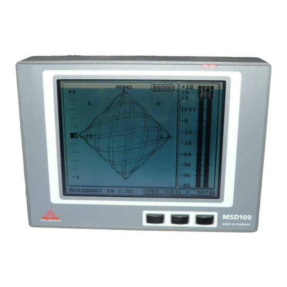
P E R A T I O N 4 -1 . M S D 1 0 0 M I G U R E A I N I S P L A Y 4.1.1 I NITIAL ISPLAY AT OWER After power up, the LCD panel initially displays the software version installed, for example MSD100 1.54. -
Page 29: Additional Information Displayed On
P E R A T I O N This operation applies to other functions such as Left, Right, Hold and Fast. The function keys are also used to increase and decrease values as shown below. 4.1.3 A DDITIONAL NFORMATION ISPLAYED ON IGITAL ODELS In addition to the phase meter, audio vector oscilloscope,... -
Page 30: Phase Correlation Meter
P E R A T I O N Note: If no signal is present, this numeric field will indicate [OPEN]. 4 . 2 P H A S E O R R E L A T I O N E T E R The Phase Correlation Meter displays the average phase relationship between two audio signals, and indicates mono, stereo or reverse-phase on a center-zero scale. -
Page 31: Peak Programme Meter (Ppm)
P E R A T I O N The best example of a true stereo signal is from an audience applauding during a live recording. This is represented graphically on the oscilloscope as a perfect circle or ball, as shown in Figure 4-3. See the examples of phase meter and oscilloscope displays under different signal conditions in Figure 4-3. -
Page 32: International Ppm Scales Supported
P E R A T I O N • Maintaining constant sensitivity of the device, optimizing use of the transmission channel and recording medium. • Using a full-wave rectifier with integration time set for highest amplitude without overloading the transmission link and for sufficient duration to avoid audible distortion. -
Page 33: Level Meters
P E R A T I O N 4 -4 . A P P M S I G U R E V A I L A B L E C A L E S 4 . 5 L E V E L E T E R S The MSD100 Level Meter provides these additional functions:... -
Page 34: Using The Utilities Menu
P E R A T I O N 4 . 7 U S I N G T H E T I L I T I E S E N U You can use the Utilities [UTIL] menu to: • Adjust display brightness •... -
Page 35: Adjusting Viewing Angle (Contrast)
P E R A T I O N Press function keys for to increase or decrease brightness. This adjusts the background lighting for the best viewing clarity. When finished, press [EXIT] to return to the Main Menu. 4.7.2 A DJUSTING IEWING NGLE ONTRAST... - Page 36 P E R A T I O N When finished, press [EXIT] to return to the Main Menu. 4.7.3 S ELECTING NVERTED I S P L A Y To reverse the colours so that the screen will appear black with white text and figures: Press [UTIL].
- Page 37 P E R A T I O N • Pflichtenhefte 3/6 • IEC 68-17 VU Meter • Nordic N9 • CCIT Report 292-2 • CCIT BS6840 part 10 See Figure 4-4 for available PPM scales. Note: As noted earlier, the MSD150C supports only two scales -- Nordic and DIN.
-
Page 38: Selecting Preferred Ppm Scale
P E R A T I O N To set the PPM reference level: Perform Steps 1 through 5 under Selecting Preferred PPM scale. After you press [SELECT], press the function keys for to set the reference level. After you set the level, press [EXIT] to return to the Main Menu. -
Page 39: Using The Ppm Fast Mode
P E R A T I O N Press [UTIL]. Press [PPM]. Press [OPTION]. The menu text line displays TOGGLE PPM OPTION. Press [HOLD] to toggle the Peak HOLD function ON or OFF. When ON, the checkbox next to HOLD is black. -
Page 40: Changing Default Settings
P E R A T I O N 4 . 9 C H A N G I N G E F A U L T E T T I N G S You can change the factory set defaults settings for brightness, viewing angle (contrast) and preferred scale. - Page 41 P E R A T I O N 4 . 1 0 B I T S T R E A M T A T U S I S P L A Y The Bitstream Status Display is used for viewing status information for each AES/EBU channel, provided that this information is available in the signal.
-
Page 42: Consumer Decoding Mode
P E R A T I O N between audio Primary/secondary mode (chan 1 is primary) signals in the two Stereo, channel 1 is left channel channels) Reserved for user-defined data One chan double sampling frequency One chan stereo: left-double sampling freq. One chan-stereo: right double sampling freq Multi-channel, vector for byte 3 User Bit... -
Page 43: Displaying Channel Information
P E R A T I O N o Magnetic tape or disk o Digital audio broadcast o Music instrument, microphone or other digital source 4.10.3 D ISPLAYING HANNEL NFORMATION To display the Channel A information, press [A DATA]. To display the Channel B information, press the same key again. - Page 44 P E R A T I O N make it possible to analyse frequency response, noise, and intermodulation (IM) distortion with much greater accuracy. Figure 4-6 shows the FFT Spectrum Analyser display on the MSD100-SA. 4-7. FFT S IGURE PECTRUM NALYSER To select the FFT Spectrum Analyser mode: Press [FFT].
-
Page 45: 1/3-Octave Spectrum Analyser
P E R A T I O N Press [LEFT] or [RIGHT] to select the left or right input signal for FFT analysis. A small black square indicates the input selected. It toggles on or off as the key is pressed. Note: To analyse a mono signal, press both [LEFT] and [RIGHT] keys. - Page 46 P P E N D I X P E C I F I C A T I O N S This appendix lists the performance specifications for the MSD100 Series. A . 1 P O W E R U P P L Y...
- Page 47 P E C I F I C A T I O N S Division of scale: Type I -42 dB to +12 dB Type IIA 1 to 7 Type IIB -12 dB to +12 dB Type DIN - 50dB to +5 dB Type VU -20 dB to +3 dB DMU1...
- Page 48 P E C I F I C A T I O N S A . 5 A U D I O E C T O R S C I L L O S C O P E Automatic gain adjusting 30 dB, default range Phase error between...
- Page 49 L O S S A R Y This glossary defines terms, acronyms and abbreviations used in this manual. Ampere; A unit of current measurement. Alternating current. Analogue-to-Digital converter. A circuit that converts a digital signal to an analogue signal. Also expressed as A/D.
- Page 50 L O S S A R Y Bandwidth The distance between the 3 dB cut-off frequencies on a response curve. Expressed in octaves or Hz. CCFT Cold Cathode tube unit used for background illumination. Codec A circuit that integrates key audio data conversion and control functions into a single integrated circuit.
- Page 51 L O S S A R Y Emphasis The requisite frequency correction upon recording and playback in order to obtain a proper frequency response. EPROM Erasable Programmable Read-Only Memory. A program storage media. Fast Fourier Transformation (FFT) Fast Fourier Transformation. A spectrum analyser using this complex FFT algorithm outperforms earlier analogue counterparts in the number of frequency bands and indication range.
- Page 52 L O S S A R Y Light-Emitting Diode. Octave A measure of bandwidth. Peak HOLD Circuit which for a shorter or longer period of time is in a position to maintain a peak value display. Peak Programme Meter (PPM) An instrument that provides direct measurement of the peak values of complex electrical signals.
- Page 53 L O S S A R Y SP/DIF Sony Philips Digital Interface defined as the consumer format. Spectrum Analyser An instrument used for determining frequency content (energy distribution) of a signal. Stereo Image Monitor See audio vector oscilloscope. Volt; Unit of measure of electrical potential (voltage). Volume Unit.
- Page 54 E G I S T R A T I O N Please fill in the registration card that was enclosed with your MSD product and mail or fax it to DK-Audio to obtain the latest information about new products. If your Registration Card is missing, you may use this page instead.
-
Page 55: Index
N D E X Consumer decoding mode 4 -17 1/3 Octave Continuous time Spectrum filter 2 -5 Analyser 4 -1 9 Contacting DK- Audio 1 -5 Contrast (viewing ADC (analogue-to- angle), digital converter) 2 -5 adjusting 4 -8, AES/EBU decoding 4 -9 mode 4 -15 Control keys 4 -1... - Page 56 N D E X Level Meter 2 -1, 4-7 EBU scale 4 -6 EPROM 2-7 Main display 4 -1 Menu text line 4 -1 Models 1 -2 Fast Fourier Model comparison Transformation table 2-7 4 -1 7 Mounting bracket Fast mode 4 -13 3 -1 Features 2 -1 FFT-Spectrum...
- Page 57 N D E X PPM scales 4-5, 4-7, 4-8, 4-10 Data Mem 2-6 Progr. Mem 2-6 Reference level selection 4-7, 4 -11 Related documentation 1-5 Sampling rate 2 -6 Scales 4 -7 Select preferred PPM scale 4-10 Settings, changing default 4 -14 Signal to noise 2 -6 Spectrum analyser 4 -17, 4 -18, 4-19...
Need help?
Do you have a question about the MSD100 Series and is the answer not in the manual?
Questions and answers