Advertisement
Quick Links
IDS Training Guide
IDS Xwave Wireless
Introduction
IDS have innovatively introduced their Xwave wireless technology to the well-renowned
and trusted Optex Detectors.
This guide provides basic steps to configure the IDS Optex Xwave Wireless Detectors.
The guide will cover installing your detector correctly, and what situation each detector
is designed for. Although this guide does give detailed steps, an understanding and
knowledge of alarm systems and concepts should be known.
Advertisement

Related Manuals for IDS Optex Xwave

Summary of Contents for IDS Optex Xwave
- Page 1 IDS have innovatively introduced their Xwave wireless technology to the well-renowned and trusted Optex Detectors. This guide provides basic steps to configure the IDS Optex Xwave Wireless Detectors. The guide will cover installing your detector correctly, and what situation each detector is designed for.
- Page 2 The IDS Xwave wireless transmitters transmit on the 433MHz range, and is designed to work with the IDS Xwave wireless receivers. There are two variants of the IDS Xwave wireless transmitters, 600-R563-01-A which is designed to fit into the outdoor sensors, and the 600-R563-02-A which is designed to fit the indoor detectors.
- Page 3 2.1. X-Series Wireless Receiver For the IDS Optex Xwave Wireless Detectors to work with the IDS X-Series panel, you will need an IDS Xwave Wireless Receiver connected on the X-Series Bus. NB: The IDS Xwave Receivers do not support the Duevi range of detectors; similarly the Duevi Receiver does not support the IDS Xwave detectors.
- Page 4 2.3. Supervision Supervision time is the time that the system waits to receive a check-in signal or a violation signal. The X-Series system has two settings: - 3 hours - 24 hours Each device can be set to send a check-in signal every 90 minutes or 12 hours. This means that if the system is set to a supervision time of “3 hours”...
- Page 5 The 860-07-587 door contact has a built-in wireless transmitter. 3.1. Hardware Transmit LED Supervision Jumper J1 On – 90 mins IDS Wireless J1 Off – 12 hrs Transmitter Tamper Switch LED Jumper On – Enables the LED Off – Disables the LED...
-
Page 6: Installation
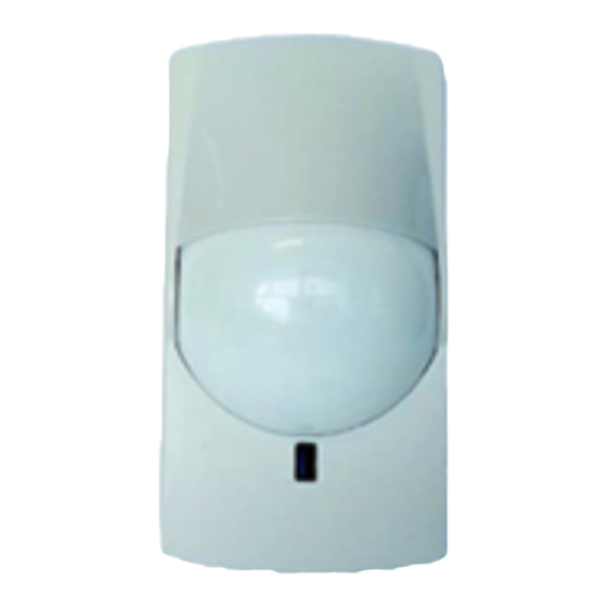
3.2. Installation Mount the wireless door contact to the door frame via the mounting holes. (Making sure that the base does not extrude passed the frame and catch on the door when it opens or closes.) Close the door and mount the magnet onto the door next to the reed switch. (Make sure that the magnet does not interfere with the wireless door contact when opening and closing the door. - Page 7 4. 862-01-WNX-40PI-T The 862-01-WNX-40PI-T is a highly reliable indoor PIR detector. 4.1. Hardware Supervision Jumper IDS Wireless J1 On – 90 mins Transmitter J1 Off – 12 hrs Walk Test Jumper On – Enables Walk Test (LED is Tamper Switch enabled, Pulse Count set to 1) Off –...
-
Page 8: Detection Area
Pulse Count is the amount of times the detector needs to be triggered within a 20 second period before an alarm condition is sent. When the 862-01-WNX-40PI-T detector is in Normal Operation it will only send an alarm after a wait period of 120 seconds from the last alarm condition. LEDs Warm-up –... - Page 9 4.3. Installation Decide where to mount your 862-01-WNX-40PI-T detector, mounting height must be 1.5m – 2.4m. Set the jumper settings (seen in the Hardware section) to your needs. Leave the Walk Test jumper ON to allow for testing. Choose the Pulse Count you require by using the Pulse Count jumper (seen in the Hardware section.) Do a thorough Walk Test.
- Page 10 The 862-01-WFX-360-1B with its highly durable spherical lens which offers unparalleled 360° detection performance. 5.1. Hardware Supervision Jumper IDS Wireless J1 On – 90 mins Transmitter J1 Off – 12 hrs Walk Test Jumper On – Enables Walk Test (LED is Tamper Switch enabled, Pulse Count set to 1) Off –...
- Page 11 LEDs Warm-up – Red LED blinks for approximately 30 seconds Alarm Condition – Red LED turns on for 2 seconds 5.2. Detection Area The 862-01-WFX-360-1B has a detection range of up to 12 metres at a 360° angle, depending on the installation height. Top view of detection area Side view of detection area Installation Height...
- Page 12 5.3. Installation Decide where to mount your 862-01-WFX-360-1B detector, mounting height should be 2.4m – 3.6m. Set the jumper settings (seen in the Hardware section) to your needs. Leave the Walk Test jumper ON to allow for testing. Choose the Pulse Count you require by using the Pulse Count jumper (seen in the Hardware section.) Do a thorough Walk Test.
- Page 13 6. 862-01-EX-35RC The 862-01-EX-35RC is a very versatile indoor PIR detector that allows for Wide Angle or Long Range detection with the benefit of a pet alley feature. 6.1. Hardware Safety Tab Break off tab when using lens in Long Range Lens Cover Battery Holder...
- Page 14 Pet Alley Mode allows a corridor beneath the detector that allows pets to move without detection. Loosen the PCB screw and slide the PCB up or down to line up with either the Pet Alley or Normal indicators according to the desired detection pattern. IDS Wireless Transmitter Supervision Jumper J1 On –...
- Page 15 6.2. Detection Area With the 862-01-EX-35RC you can select either Wide Angle detection or Long Range detection. You also have the option of a Pet Alley mode that gives the detection an “alley” for pets to move undetected. To select either Wide Angle or Long Range detection, remove the lens from the detector, and change its orientation.
- Page 16 Wide Angle Pet Alley Mode Wide Angle Mounting Height/Detection Distance Mounting 0.6m 0.9m 1.2m 1.5m 1.8m 2.1m 2.4m Height Normal 4.5m Mode Pet Alley Mode Long Range Top View Long Range detection will detect up 17m at a narrow angle. Long Range Side View...
- Page 17 Long Range Pet Alley Mode Long Range Mounting Height/Detection Distance Mounting 0.6m 0.9m 1.2m 1.5m 1.8m 2.1m 2.4m Height Normal 12.5m Mode Pet Alley 12.5m Mode 6.3. Installation Decide where to mount your EX-345RC detector, the mounting height for Normal Mode should be 1.2m - 2.4m and for Pet Alley Mode should be 0.6m –...
- Page 18 7. 862-01-CX-702RSC The 862-01-CX-702RSC is an indoor PIR detector with the ability to do either wide angle or long range detection. 7.1. Hardware Battery Holder 2 x AA Batteries Lens Cover...
- Page 19 When the 862-01-CX-702RSC detector is in Normal Operation it will only send an alarm after a wait period of 120 seconds from the last alarm condition. IDS Wireless Transmitter Supervision Jumper J1 On – 90 mins J1 Off –...
- Page 20 7.2. Detection Area The 862-01-CX-702RSC has a variety of option detection area options. You can select Wide Angle detection or Long Range detection. You can also adjust the vertical angle according to your desired detection range. Lens Holder Lens To select either Wide Angle or Long Range detection, remove the lens holder from the detector, and change the orientation of the lens.
- Page 21 Wide Angle Side View Long Range Top View Long Range detection will detect up to 45m at a narrow angle. Long Range Side View You can adjust the vertical angle to change the detection distance. To do this, clip the lens into the lens holder at either position A, B or C.
- Page 22 Long Range Detection Detection Distance Mounting 1.8m Height 2.4m 3.6m 7.3. Installation Decide where to mount your CX-720RSC detector, the mounting height should be 1.5m, 2.4m or 3.6m. Set the detector to either Long Range or Wide Angle and set the Vertical Adjustment as desired (seen in the Detection Area section.) Make sure the Walk Test jumper is ON to allow for testing.
- Page 23 8. VX Infinity Series There are three detectors in the VX Infinity Series; 862-01-VXI-R which has two PIR lenses, 862-01-VXI-RAM which has two PIR lenses with anti-masking functionality, and 862-01-VXI-RDAM-X5 which has two PIR lenses and a microwave sensor with anti-masking functionality. 8.1.
- Page 24 Dip Switch Dip Switch 1 - Walk Test Mode Position Function Test Mode On. The LED lights irrespective of the Dip switch 4 setting. Dip switch 2, Battery Saving Timer, is inactive. Normal Mode. LED and Battery Saving Timer works according to their setting.
- Page 25 LEDs VXI-R and 862-01-VXI-RAM Warm-up – Red LED blinks for approximately 60 seconds Alarm Condition – Red LED turns on for 2 seconds Masking Detection (862-01-VXI-RAM Only) – Red LED blinks 3 times and then repeats 862-01-VXI-RDAM-X5 Warm-up – Red and Yellow LEDs blink for approximately 60 seconds PIR Detection –...
- Page 26 IDS Wireless Transmitter Supervision Jumper J1 On – 90 mins J1 Off – 12 hrs Power Connector Detector Inputs Connect the battery Tamper & PIR inputs holder lead here. come from the detector. Battery Holder 2 x AA Batteries Tamper Switch 8.2.
- Page 27 Position 1 Position 2 Position 3 Position 4 Position 5 The detection area angle can be adjusted by holding where is says ‘Hold to turn’ and turning the sensor plate left or right. The Area Angle Adjustment indicates what angle you have selected.
- Page 28 There are 16 zones of PIR detection on all angles except angle A and G, which only have 14 zones of PIR detection. The red beams represent the PIR detection zone. The blue line represents the microwave detection area. Angle A Angle B Angle C Angle D...
- Page 29 8.3. Area Masking In the event that there are objects, such as a bush or a pool, inside the detection area, you are able to block certain zones by applying an area masking label. In this situation you have a small tree that will give you false alarms if not masked. 1.
- Page 30 4. Place the strip in the I zone of the lens, and replace the lens and lens holder back into the cover. Masking strip This will now mask the I zone, preventing the tree from causing any alarms. 8.4. Installation Decide where to mount your VX-Infinity detector, mounting height must be 0.8m –...
- Page 31 9. 862-01-HX-40RAMC The 862-01-HX-40RAMC is an intelligent pet friendly outdoor detector with two PIR lenses and Anti-Masking protection. 9.1. Hardware Tamper Switch Top PIR Lens Dip Switch 1 – Walk Test Mode 2 – Battery Saving Timer 3 – Immunity 4 –...
- Page 32 Dip Switch Dip Switch 1 - Walk Test Mode Position Function Test Mode On. The LED lights irrespective of the Dip switch 6 setting. Dip switch 2, Battery Saving Timer, is inactive. Normal Mode. LED and Battery Saving Timer works according to their setting.
- Page 33 LEDs Alarm – Red LED turns on for 2 seconds Warm-up – Red LED blinks for approximately 90 seconds Anti-Masking Start Up – Red LED blinks 2 times every 5 seconds Anti-Masking Detection – Red LED blinks 3 times every 3 seconds Low Battery –...
- Page 34 IDS Wireless Transmitter Supervision Jumper J1 On – 90 mins J1 Off – 12 hrs Power Connector Detector Inputs Connect the battery Tamper & PIR inputs holder lead here. come from the detector. Battery Holder Holds 3 x CR 123A batteries 9.2.
- Page 35 With an installation height of 3.0m the detection length is 12m. You can shorten the detection length by using masking seals. To apply the masking seals, remove the lens from the lens cover, and apply the seals to the lens. Masking seal 1 will give you 9m.
- Page 36 Masking seal 1 & 2 will give you 5.5m. Masking seal 1, 2 & 3 will give you 4m. You can also use masking strips to block of certain detection zones. Masking strip...
- Page 37 9.3. Installation Decide where to mount your 862-01-HX-40RAMC, the detector must be parallel to the ground for best performance. If the ground is not flat, adjust the vertical angle of the mounting bracket until the detector is parallel to the ground. The suggested mounting height is 3.0m.
- Page 38 10. HX-80NRAM The 862-01-HX-80NRAM is an intelligent long range outdoor detector with two PIR lenses and Anti-Masking protection. 10.1. Hardware Tamper Switch Top Masking Flap Dip Switch Top PIR Lens 1 – Walk Test Mode 2 – Battery Saving Timer 3 –...
- Page 39 IDS Wireless Transmitter Battery Holder IDS Wireless Transmitter Supervision Jumper J1 On – 90 mins J1 Off – 12 hrs Power Connector Detector Inputs Connect the battery Tamper & PIR inputs holder lead here. come from the detector. Battery Holder...
- Page 40 Dip Switch Dip Switch 1 - Walk Test Mode Position Function Test Mode On. The LED lights irrespective of the Dip switch 6 setting. Dip switch 2, Battery Saving Timer, is inactive. Normal Mode. LED and Battery Saving Timer works according to their setting.
- Page 41 Dip Switch 7 – AND/OR Position Function OR Mode, an alarm is generated when either PIR's are triggered. AND Mode, an alarm is generated when both top and bottom PIRs are triggered. NB: When the detector is in OR Mode there is a larger chance of false detections, as only 1 PIR needs detection.
- Page 42 Side View Masking Flap Masking Plate There are 2 Masking plates and 2 Masking Flaps, one each for the top PIR and one each for the bottom PIR. The Masking Flaps are used to mask the long distance detection zones, i.e. shortening the detection distance. The Masking Plates are used to mask the short range detection area, i.e.
- Page 43 2.) Put the Top Masking Flap to position A and the Bottom Flap to B. Detection length is 13m. 3.) Put the Top Masking Flap to position C and the Bottom Flap to B. Detection length is 10m. 4.) Put the Top Masking Flap to position C and the Bottom Flap to D. Detection length is 6.5m.
- Page 44 3.) Put the Top Masking Plate to position I and the Bottom Masking Plate to position H. No detection within 4m of the detector. 4.) Put the Top Masking Plate to position G and the Bottom Masking Plate to position H. No detection within 5m of the detector. 10.3.
- Page 45 11. FTN Series The FTN Series has two detectors; both with two PIR lenses and both are designed to be wall-mounted and give up to 5 metres of detection with a width of 1 metre. The FTN detectors can be rotated horizontally 190°. The 862-01-FTN- RAM detector has an anti-masking function to prevent covering of the detector.
- Page 46 IDS Wireless Transmitter Supervision Jumper J1 On – 90 mins J1 Off – 12 hrs Power Connector Detector Inputs Connect the battery Tamper & PIR inputs holder lead here. come from the detector. Battery Holder Holds 1 x CR 123A...
- Page 47 Dip Switch 2 – Battery Saving Timer Position Function Even if there are continuous alarms, the alarm is only generated once in a 5 second time. Even if there are continuous alarms, the alarm is only generated once in a 120 second time. To lengthen battery life. Dip Switch 3 –...
- Page 48 11.2. Detection Area The FTN Series of detectors have a narrow detection area with up to 5m detection length. You can rotate the detector 190° to give you a wall of protection in any direction. To rotate the detector, remove the fixture (shown on the right) and turn the detector to the desired horizontal angle.
- Page 49 To change the detection length between 5m and 2m, remove the lower lens and rotate it to the desired position. There is a 5m and a 2m label on the lens cover, the chosen detection length will be visible. NB: Do not change the orientation of the upper lens. 5m Detection Length 2m Detection Length 11.3.
- Page 50 12. 862-01-BX-80NRC The 862-01-BX-80NRC is designed to be wall-mounted centrally on a building. It gives up to 24 metres of protection, 12 metres on either side of the detector. 12.1. Hardware LED Indicator LED Indicator Dip Switch PIR Sensitivity Selector 1 –...
- Page 51 IDS Wireless Transmitter Supervision Jumper J1 On – 90 mins J1 Off – 12 hrs Detector Inputs Tamper & PIR inputs Power Connector come from the Connect the battery detector. holder lead here. Battery Holder Holds 2 x AA batteries...
- Page 52 Dip Switch Dip Switch 1 - Walk Test Mode Position Function Test Mode On. The LED lights irrespective of the Dip switch 6 setting. Dip switch 2, Battery Saving Timer, is inactive. Normal Mode. LED and Battery Saving Timer works according to their setting.
- Page 53 12.2. Detection Area The 862-01-BX-80NRC has a detection length of up to 12 metres per side. The detection area can be adjusted in two ways: The angle of the beams from the wall and the detection length. Both detection adjustments require the lens holder to be removed from the front cover, as seen below.
- Page 54 Detection Area at 0° Detection Area at 3° NB: Avoid adjusting just the upper or lower lens as the detector requires both upper and lower beams to be broken. The upper detection beam stays parallel to the ground, to adjust the detection length you must slide the lower lens up or down to the appropriate position.
- Page 55 Position C – 5 metres Position D – 2 metres 12.3. Installation Decide where to mount your 862-01-BX-80NRC, keeping in mind the detector detects on both sides of the detector. The suggested mounting height is 0.8m –1.2m. Set the dipswitch settings (seen in the Hardware section) to your needs. Leave dipswitch 1 ON to allow for the walk test.
- Page 56 13. AX-Series The AX Series of beams come in two versions, 30 metres and 60 metres. These photoelectric beams are very customisable to suit your situation and to prevent interference. 13.1. Hardware The AX Beams come in pairs, a transmitter and a receiver. The transmitter sends a beam to the receiver and when that beam is broken then an alarm condition occurs.
- Page 57 Battery Holder Holds 2 x LSH 20 batteries Tamper Switch Dip Switch Dip Switch 1 - Battery Saving Timer Position Function Even if there are continuous alarms, the alarm is only generated once in a 120 second time. To lengthen battery life. The alarm is generated whenever there is an alarm condition.
- Page 58 Voltage Monitor Jack View Finder Beam Frequency Selection Vertical Alignment Dial Horizontal Alignment Dial IDS Wireless Transmitter Supervision Jumper J1 On – 90 mins J1 Off – 12 hrs Detector Inputs Power Connector Tamper & PIR inputs Connect the battery come from the holder lead here.
- Page 59 Dip Switch Dip Switch 1/2 – Beam Interruption Adjustment Dipswitch Position Running Jogging Walking Slow Movement Interruption Time Setting (50 msec) (100 msec) (250 msec) (500 msec) Dip Switch 3 - Battery Saving Timer Position Function Even if there are continuous alarms, the alarm is only generated once in a 120 second time.
- Page 60 13.2. Aligning Beams Beams must be aligned correctly for optimal detection and reduced false alarms. While looking through viewfinder, adjust the horizontal and vertical angles until the pairing detector is in the centre of the sight. Use the Alarm Indicator LED on the Beam Receiver for a rough alignment.
- Page 61 To adjust the horizontal angle hold and turn the lens holder left or right. You can make fine adjustments using the horizontal alignment dial. To adjust the vertical angle of the lens, turn the vertical alignment dial. Counter-clockwise turns the Clockwise turns the lens lens downwards.
-
Page 62: Installation Recommendation
14. Installation Recommendation For optimum performance and reduced risk of false alarms, please follow these installation recommendations. 14.1. Indoor Detectors Be aware of temperature altering appliances in the detection area. Placing a heater or air-conditioner in the detection area can cause false alarms. Avoid installing the detector where it will get direct sunlight. - Page 63 14.2. Outdoor Detectors When installing any PIR detectors you must take into account that it detects change in temperature. This is especially important outdoors as the sun and trees move about causing these changes in temperature. Avoid installing detectors with moving trees and bushes in the Be aware of reflective surfaces detection area.
Need help?
Do you have a question about the Optex Xwave and is the answer not in the manual?
Questions and answers