Table of Contents
Advertisement
Quick Links
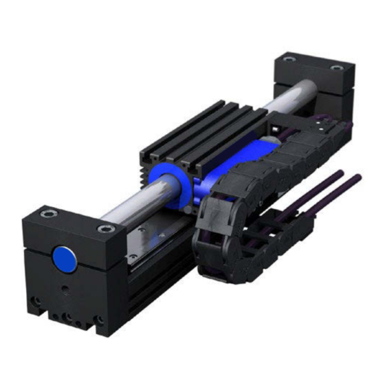
ServoTube 25 / 38 Module
User guide
Operating Manual ServoTube 25/38 Module
Publication Ref: UM03016/B
Betriebanaleitung ServoTube 25/38 Module
Publikation Ref: UM03016/B
Dunkermotoren GmbH | Allmendstraße 11 | D-79848 Bonndorf/ Schwarzwald
Phone +49 (0) 7703 930-0 | Fax +49 (0) 7703 930-210/ 212 | info@dunkermotoren.com
Advertisement
Table of Contents

Summary of Contents for dunkermotoren ServoTube 25 / 38
-
Page 1: Preliminary Pages Title Page
User guide Operating Manual ServoTube 25/38 Module Publication Ref: UM03016/B Betriebanaleitung ServoTube 25/38 Module Publikation Ref: UM03016/B Dunkermotoren GmbH | Allmendstraße 11 | D-79848 Bonndorf/ Schwarzwald Phone +49 (0) 7703 930-0 | Fax +49 (0) 7703 930-210/ 212 | info@dunkermotoren.com... -
Page 2: Copyright Notice / Disclaimer
Dunkermotoren. DISCLAIMER Dunkermotoren makes no guarantees of any kind with regard to this User Guide. Dunkermotoren shall not be liable for errors contained herein or for consequential or incidental damages incurred as a result of acting on information contained in the manual. -
Page 3: Table Of Contents
Chapters Product overview ....................6 Installation ......................7 Maintenance ......................12 Service ......................... 23 Appendices A Glossary of terms & Abbreviations ............... 24 B Trouble Shooting ....................26 C Technical Specification ..................27 Version 03.2018 | Page/ Seite 3 www.dunkermotoren.com... -
Page 4: Warnings
• Use 360 degree screen terminations where possible. “Pig-tail” terminations are not recommended. • Ensure compliance with any local electrical and EMC regulations in force at the time of installation. This is the responsibility of the User. Version 03.2018 | Page/ Seite 4 www.dunkermotoren.com... -
Page 5: Reader's Notes
ASSOCIATED PUBLICATIONS The following publications are associated with the ServoTube 25/38 Module User Guide. Title Reference Number ServoTube 25/38 Module Data sheet DS01100 Copley Xenus (XTL-S) User Guide Copley Xenus (XTL-S) Data Sheet Version 03.2018 | Page/ Seite 5 www.dunkermotoren.com... -
Page 6: Chapters
Amplifiers interface easily to PLCs and feature CANopen network connectivity for distributed magnetic design ServoTube generates control applications. 12 micron repeatability 350 micron absolute Version 03.2018 | Page/ Seite 6 www.dunkermotoren.com... -
Page 7: Installation
• On the SM25 modules, the fixings are M5 and should be tightened to a torque of 12 Nm. • On the XM38 modules, the fixings are M6 and should be tightened to a torque of 20 Nm. Version 03.2018 | Page/ Seite 7 www.dunkermotoren.com... - Page 8 L = Length in mm SM25 STROKE TABLES Stroke Stroke Length Length 2504 2506 2508 2510 2504 2506 2508 2510 1022 1073 1125 1176 1227 1279 1049 1330 1100 1049 1381 1151 1100 1049 Version 03.2018 | Page/ Seite 8 www.dunkermotoren.com...
- Page 9 1073 1002 1407 1109 1038 1443 1145 1074 1003 1478 1180 1109 1038 1514 1216 1145 1074 1003 1550 1252 1181 1110 1039 1585 1287 1216 1145 1074 1621 1323 1252 1181 1110 Version 03.2018 | Page/ Seite 9 www.dunkermotoren.com...
- Page 10 Black 1 Forcer phase U Black 2 Forcer phase V Black 3 Forcer phase W Green/Yellow Earth (forcer body) Screen Shell SCREEN 4-way 5mm 4-way pluggable pluggable Connector type terminal terminal Amplifier connection Version 03.2018 | Page/ Seite 10 www.dunkermotoren.com...
- Page 11 CAUTION. It is strongly recommended that the forcer over-temperature sensor is connected to the drive amplifier or servo controller at all times in order to reduce the risk of damage to the forcer due to excessive temperatures. Version 03.2018 | Page/ Seite 11 www.dunkermotoren.com...
-
Page 12: Maintenance
The bearing system must only be lubricated via the bearing carriages. Do not lubricate the bearing rail. Do not lubricate the thrust rod, it is not a bearing surface. Version 03.2018 | Page/ Seite 12 www.dunkermotoren.com... - Page 13 Version 03.2018 | Page/ Seite 13 www.dunkermotoren.com The grease gun nozzle does not attach itself to the bearing carriage lubrication nipple, so opposing pressure will need to be applied to the grease gun and the forcer, to ensure the grease is going into the bearing carriage during re-greasing.
- Page 14 The encoder scale should be cleaned with a soft, lint free cloth to remove any oil, grease or dirt. Under no circumstances must solvents be used on optical encoder scales as the protective lacquer coating may become damaged. Version 03.2018 | Page/ Seite 14 www.dunkermotoren.com...
- Page 15 • Remove any cable ties that have been used to hold the cables in position. Figure 3.3 • With the cover section removed the cables can now be removed from the drag chain, see Figure 3.4. Figure 3.4 Version 03.2018 | Page/ Seite 15 www.dunkermotoren.com...
- Page 16 TB1 and PL1. • Plug PL1 into its connector on the edge-mounted PCB. • Connect the power cable leads to TB1 and the earthing point. Refer to Figure 3.6 for the connection table. Version 03.2018 | Page/ Seite 16 www.dunkermotoren.com...
- Page 17 » Only handle one rod at a time » Never remove safety sleeving if not absolutely necessary, and handle/transport the thrust rods in the original packaging » Never use thrust rod, if it appears damaged Version 03.2018 | Page/ Seite 17 www.dunkermotoren.com...
- Page 18 • Carefully slide the thrust rod out through the thrust rod supports and forcer (Figure 3.13) until it is clear of the module assembly, see Figure 3.14. • Store the thrust rod in a safe place away from ferrous material. Figure 3.14 Version 03.2018 | Page/ Seite 18 www.dunkermotoren.com...
- Page 19 If balls do fall out they can be re-inserted into the carriages. Push the ball bearings using a small screwdriver into the end of the re-circulating path at the plastic end plates on the carriage. Figure 3.16 Version 03.2018 | Page/ Seite 19 www.dunkermotoren.com...
- Page 20 8 mm below and parallel to the datum edge • The encoder readhead bracket fitted with the encoder readhead (optional items) • The limit switch actuator (optional). • The drag chain upper mounting bracket. Figure 3.20 Version 03.2018 | Page/ Seite 20 www.dunkermotoren.com...
- Page 21 If balls do fall out they can be re-inserted into the carriages. Push the ball bearings using a small screwdriver into the end of the re-circulating path at the plastic end plates on the carriage. Version 03.2018 | Page/ Seite 21 www.dunkermotoren.com...
- Page 22 Should excessive play be detected in the bearing system the bearing will need replacing. It is recommended that all bearing carriages and the bearing rail are replaced at the same time. Due to the complex nature of the process and specialist equipment required, please contact your supplier regarding replacement. Version 03.2018 | Page/ Seite 22 www.dunkermotoren.com...
-
Page 23: Service
Service SERVICE Should you need to return any items to Dunkermotoren, before doing so, please call our Sales coordinator in order to obtain an RMA (Returned Materials Authorisation) number. The RMA number should then be quoted on all items returned and quoted for all enquiries. -
Page 24: A Glossary Of Terms & Abbreviations
Continuous working voltage is the maximum allowable continuous voltage between any two forcer phases or between any forcer phase and the forcer safety earth. voltage Pole pitch Pole pitch is the distance in millimetres for one complete electrical cycle (between like magnetic poles). Version 03.2018 | Page/ Seite 24 www.dunkermotoren.com... - Page 25 Electro-Motive Force Underwriters Laboratory kilogramme Volt metre Volt peak milliampere Vpk-pk Volt peak to peak millihenry Vrms Volt root mean square millimetre Watt Mounting °C degrees Celsius Newton micrometre (micron) Positive Temperature Coefficient Version 03.2018 | Page/ Seite 25 www.dunkermotoren.com...
-
Page 26: B Trouble Shooting
Forcer moves in wrong One or more position sensor and forcer Check position sensor and forcer phase direction. phase connections made incorrectly. connections on drive. Version 03.2018 | Page/ Seite 26 www.dunkermotoren.com... -
Page 27: C Technical Specification
Inductance @ 1kHz (phase to phase) 3.90 0.97 5.85 1.46 7.80 1.95 9.75 2.44 Electrical time constant 0.65 Maximum working voltage V d.c. Pole pitch (one electrical cycle) 51.2 Peak acceleration Maximum speed Version 03.2018 | Page/ Seite 27 www.dunkermotoren.com... - Page 28 S=series forcer phases, P=parallel forcer phases Reduce continuous stall force to 89% at 40 C ambient Based on a moving forcer with to payload Based on a moving forcer with triangular move over maximum stroke and no payload Version 03.2018 | Page/ Seite 28 www.dunkermotoren.com...
- Page 29 For a bearing life expectancy of 10000 km with no other forces or moments For a bearing life expectancy of 100000 km with no other forces or moments Load in kg = force/9.81 Version 03.2018 | Page/ Seite 29 www.dunkermotoren.com...
- Page 30 TTL signals, you can join up in circuit an additional inter- eingang mit 5V TTL Pegel verarbeiten können, so kann face converter (SI10). ein zusätzlichen Schnittstellenwandler (SI10) dazwi- For more information, see Documentation SI10. schengeschalten werden. Nähere Infos siehe Doku SI10. Version 03.2018 | Page/ Seite 30 www.dunkermotoren.com...
- Page 31 Screened / Unscreened Screened Screened Minimum bending radius - flexible 42mm 42mm routing Operating temperature - flexible C to +80 C to +80 routing Operating temperature - flxed C to +80 C to +80 routing Version 03.2018 | Page/ Seite 31 www.dunkermotoren.com...
- Page 32 The ServoTube Module is intended for use in an environment within the following conditions: SPECIFICATION VALUE Operating temperature C to +40 Storage temperature C to +70 Altitude (above mean sea 1000m level) Overvoltage category Pollution degree light industrial Version 03.2018 | Page/ Seite 32 www.dunkermotoren.com...
Need help?
Do you have a question about the ServoTube 25 / 38 and is the answer not in the manual?
Questions and answers