Table of Contents
Advertisement
Quick Links
QUICK START GUIDE
HARRIER USB/HDMI
CAMERA INTERFACE BOARD
Introduction
This guide is designed to get you quickly up and running with the
Harrier USB/HDMI Camera Interface Board (AS-CIB-USBHDMI-002-A) and the Harrier USB/HDMI
Evaluation Kit (AS-CIB-USBHDMI-001-EVAL-A). The interface board can be purchased as a pre-
assembled camera module with a range of different cameras, e.g. Tamron MP1110M/MP2030M-GS
or Harrier 36x/10x AF-Zoom Cameras. The board is configured by default for the Tamron MP1110M.
This document should be read in conjunction with the datasheet and other documents available on
Active Silicon's website,
https://www.activesilicon.com/products/harrier-usb-hdmi-camera-interface-board/
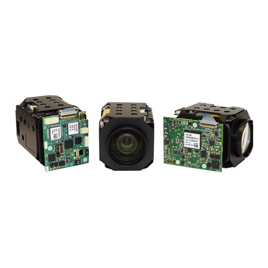
Figure 1. Harrier USB/HDMI Interface Board
mounted on a Tamron MP1110M camera
Figure 3. Harrier USB/HDMI Interface Board
mounted on a Harrier 36x AF-Zoom Camera
with global shutter
The Harrier USB/HDMI Camera Interface Board can also be supplied in HDMI- or USB-only variants.
A 3G-SDI/HD-SDI camera interface board is also available. For more details contact Active Silicon.
March 2021
HARRIER USB/HDMI CAMERA INTERFACE BOARD
(see Harrier USB/HDMI Camera Interface Board - Downloads section):
QUICK START GUIDE
Figure 2. Reverse side of Harrier USB/HDMI
Camera Interface Board
Figure 4. Interface board block diagram
showing position of connectors and DIP
switches
Version 1.7 – March 2021
Page 1 of 14
Advertisement
Table of Contents

Subscribe to Our Youtube Channel
Summary of Contents for Active Silicon HARRIER
- Page 1 Tamron MP1110M/MP2030M-GS or Harrier 36x/10x AF-Zoom Cameras. The board is configured by default for the Tamron MP1110M. This document should be read in conjunction with the datasheet and other documents available on Active Silicon’s website,...
-
Page 2: Evaluation Kit Contents
The Evaluation Kit (AS-CIB-USBHDMI-001-EVAL-A) contains all the parts needed to evaluate the Harrier USB/HDMI Camera Interface Board. Note that the Evaluation Kit does not include a Harrier USB/HDMI Camera Interface Board or camera, these need to be ordered separately. Please check that you have all the parts listed below: •... -
Page 3: Quick Start
The Harrier USB/HDMI Camera Interface Board is configured by default for the Tamron MP1110M camera, if you are using any other camera, the Harrier USB/HDMI Camera Interface Board needs to be re-configured to support the specific USB related properties of the camera. If you have purchased a pre-assembled camera unit then the board will already be correctly configured for the camera. -
Page 4: Communications Mode
Harrier Virtual COM port (if installed), or by using UVC commands. You can select which one of these you want to use by setting DIP switches 5, 6 and 7 on the Harrier USB/HDMI Camera Interface Board when the board power is off. - Page 5 This is done by setting DIP switches 1 to 4 on the Harrier USB/HDMI Camera Interface Board as shown below, please check that your camera can support the selected mode.
- Page 6 Harrier Evaluation Board Overview Figure 9. Harrier Evaluation Board diagram The Harrier Evaluation Board connects to the camera interface board using the supplied cable kit. • JTAG (J104) - white 8-way cable (connects to J4, not required in normal use).
- Page 7 AS-CIB-USBHDMI-002-1110-A, this cable will already be connected). 2. RS-232/RS-485/TTL communications: to use serial communications with the camera, connect the USB A - mini USB cable to the mini USB connector on the Harrier Evaluation Board, and connect the USB A plug to a PC USB socket.
- Page 8 Software/ HarrierControl section of www.ActiveSilicon.com. To use your own program you can use the three COM ports that are set up when the Harrier Evaluation board is plugged in. Typically, the lowest COM port number is the RS-232 interface, the middle port number is the RS-485 interface and the highest port number is the TTL interface.
-
Page 9: Test Pattern
With no video input connected, a simple blue/gray screen is displayed (see Figure 12). You may see this when the camera resets. To display a static test pattern (see Figure 13), press the PGEN button on the Harrier Evaluation Board. -
Page 10: Reset Button
Harrier USB/HDMI Camera Interface Board as the initial video device. To select video from the Harrier USB/HDMI Camera Interface Board you may need to stop the current video (using the stop button shown in Figure 15), select the Active Silicon Harrier camera (as shown in Figure 16), and start the video again. - Page 11 The actual video mode of the camera output can be easily determined by checking the format of the HDMI output of the Harrier USB/HDMI Camera Interface Board or by using a VISCA inquiry. If the output from the HDMI interface and the mode selected in the HarrierView Application are the same please check the interface board LED for error conditions and ensure that you have a USB Type C cable of the correct specification (USB3.X Type A/C to Type C,...
- Page 12 PC. Tamron Camera Control Applications are only supported on Windows Please check that the Harrier USB/HDMI Camera Interface Board DIP switches are set for the serial interface standard that you intend to use and check that you have connected the 10-way cable to the correct connector on the Harrier Evaluation Board.
-
Page 13: Supported Cameras
Active Silicon website. If the SDK is installed, DIP switch SW1 [7] on the interface board is set to ON and the Harrier USB/HDMI interface board USB port is connected to the PC with a suitable cable, the Harrier Virtual Serial COM port appears in the Device Manager COM/LPT Port list (Figure 11). - Page 14 QUICK START GUIDE HARRIER USB/HDMI CAMERA INTERFACE BOARD Version 1.7 – March 2021 Europe & APAC: Americas: Active Silicon Ltd Active Silicon, Inc. Pinewood Mews, Bond Close, Iver, 479 Jumpers Hole Road, Suite 301, Bucks, SL0 0NA, UK. Severna Park, MD 21146, USA.
Need help?
Do you have a question about the HARRIER and is the answer not in the manual?
Questions and answers