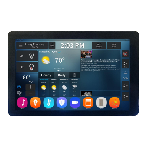
Summary of Contents for Future Design ELI101-IPHW
- Page 1 User’s Manual ELI101-IPHW ELI101-IPHW Revision 1.01 Copyright ©2018, Future Designs, Inc., All Rights Reserved...
-
Page 2: Important Legal Information
User’s Manual ELI70-IPHW Important Legal Information Information in this document is provided solely to enable the use of Future Designs, Inc. (FDI) products. FDI assumes no liability whatsoever, including infringement of any patent or copyright. FDI reserves the right to make changes to these specifications at any time, without notice. No part of this document may be reproduced or transmitted in any form or by any means, electronic or mechanical, for any purpose, without the express written permission of Future Designs, Inc. -
Page 3: Table Of Contents
User’s Manual ELI70-IPHW Important Legal Information .......................... 2 Introduction ............................4 Box Contents ............................4 Optional Accessories Recommended for Use (Purchased Separately) ..........4 ESD Warning ............................5 Determining the Revision of your ELI ....................5 Technical Specifications ........................6 Connectors ............................ -
Page 4: Introduction
Your ELI Experience Share your experience connecting ELI devices to various (single board) computers at: http://www.teamfdi.com/edid/#edidform. Box Contents • ELI101-IPHW Optional Accessories Recommended for Use (Purchased Separately) • 12V DC +/-5% 2A Power Supply with a center positive b arrel plug o 2.1mm I.D. -
Page 5: Esd Warning
User’s Manual ELI70-IPHW ESD Warning Figure 1. Electrostatic Sensitive Device Our ELI units are shipped in a protective anti-static package. Do not subject the module to high electrostatic potentials. Exposure to high electrostatic potentials may cause damage to the boards that will not be covered under warranty. -
Page 6: Technical Specifications
User’s Manual ELI70-IPHW Technical Specifications Table 1. Technical Specifications Screen Size: 10.1 inches (diagonal) Display Technology: IPS a-Si TFT LCD Resolution: 1280 x 800 (WXGA) Brightness: 690 nits (typical) Contrast Ratio: 800:1 (typ) Aspect Ratio: 16:9 Interface Input Mode: HDMI/DVI Colors: 16.7M (24 bit) Horizontal Viewing Angle:... -
Page 7: Connectors
ELI unit being used. On the ELI101-IPHW plug power into the (P2) connector. The ELI101-IPHW input power range is expanded to include +5 to 24V DC ± 5% (2.0A) for greater design flexibility. - Page 8 J6 connector (PCB terminal block - PTSM 0,5/ 2-2,5-H SMD WH R24 – 1814634) can be found at http://tinyurl.com/1814634. To verify that the ELI101-IPHW unit is correctly powered you may check the 12VDC input with a Fluke meter or scope by probing the +12V and GND contacts shown below. Please verify that the 12VDC is present, is within the +/- 5% tolerance and is free from excessive noise or AC ripple.
-
Page 9: Extended Display Information Data (Edid)
You can find out more on our website at http://www.teamfdi.com/edid/. Brightness Control ELI101-IPHW contains a Brightness Control potentiometer (VR1) on the backside of the board, see Figure 4. Using this pot, you can set the default “Factory” brightness of the LCD Backlight. Turning the pot fully clockwise results in maximum brightness of the display. - Page 10 BIOS settings aren’t compatible with ELI. This prevents the screen from showing incorrect images until the SBC has time to boot and read EDID or set the correct video timings for the ELI101-IPHW. The output at pin 1 of J3 is 3.3VDC ± 5%. If the external system is capable of directly driving the PWM dimming signal at 3.3VDC, there is no need to connect pin 1 to the cable.
- Page 11 User’s Manual ELI70-IPHW Figure 6. ELI101-IPHW Backlight Curve in Nits Note: Pot VR1 has no effect while PWM signal is applied. The J3 mating connector information: • Manufacturer: Hirose • Part Number: DF12-3S-1.25C • Digi-Key Link: https://www.digikey.com/products/en?keywords=H2180-ND • Pre-terminated wires https://www.digikey.com/products/en?PPV=1811-9-566967...
- Page 12 Figure 7. Raspberry Pi Signal and Ground The ELI backlight can be controlled from a Raspberry Pi. See Figure 7 for a wiring diagram. Our software is available on the FDI website at https://www.teamfdi.com/product-details/eli101-iphw#software or you may copy the code from here: /* Changes brightness of ELI backlight given a command line argument between 0 and the set range.
- Page 13 User’s Manual ELI70-IPHW #include<iostream> #include<bcm2835.h> #include<string> using namespace std; #define LED RPI_GPIO_P1_12 // PWM pin number for backlight control #define RANGE 20 // Range for PWM steps #define CLOCK 1920 // Clock rate int main(int argc, char *argv[]){ data = 0; // Brightness level if(argc != 2){...
- Page 14 User’s Manual ELI70-IPHW Figure 9. Renesas Synergy S7G2 Signal and Ground Another example of backlight control using a microcontroller is Renesas Synergy S7G2 wired as shown in Figure 9. The software for Synergy can be found on our website at https://www.teamfdi.com/product- details/eli70-iphw#software.
-
Page 15: Support
12.1 Where to Get Help Online technical support is available at http://www.teamfdi.com/support/ 12.2 Useful Links • Future Designs, Inc. Forums: http://www.teamfdi.com/forum • ELI101-IPHW Product Page: http://www.teamfdi.com/product-details/eli101-iphw • ELI Software User’s Manual: http://www.teamfdi.com/wp-content/uploads/ELI-Software- Users-Manual.pdf • Tell us about your ELI experience: http://www.teamfdi.com/edid/#edidform...


Need help?
Do you have a question about the ELI101-IPHW and is the answer not in the manual?
Questions and answers