Table of Contents
Advertisement
Advertisement
Table of Contents

Summary of Contents for Jungheinrich ESE 533
- Page 1 ESE 533 03.10 Operating instructions en-GB 51157401 02.21 ESE 533...
- Page 3 Declaration of Conformity Manufacturer Jungheinrich AG, 22039 Hamburg, Germany Description Industrial truck Type Option Serial no. Year of manufacture ESE 533 On behalf of Date EU DECLARATION OF CONFORMITY The undersigned hereby declare that the powered truck described in detail complies with the current versions of European Directives 2006/42/EG (Machinery Directive) and 2014/30/EU (Electromagnetic Compatibility - EMC).
- Page 5 Foreword Notes on the operating instructions The present ORIGINAL OPERATING INSTRUCTIONS are designed to provide sufficient instruction for the safe operation of the industrial truck. The information is provided clearly and concisely. The chapters are arranged by letter and the pages are numbered continuously.
- Page 6 Copyright Copyright of these operating instructions remains with JUNGHEINRICH AG. Jungheinrich Aktiengesellschaft Friedrich-Ebert-Damm 129 22047 Hamburg - Germany Tel: +49 (0) 40/6948-0 www.jungheinrich.com...
-
Page 7: Table Of Contents
Contents Correct Use and Application General Correct application Approved application conditions Proprietor responsibilities Adding attachments and/or accessories Truck Description Application Travel direction definition Assemblies and Functional Description Assembly Overview Functional Description Technical Specifications Performance data Dimensions Weights Tyre type EN norms Conditions of use Electrical Requirements Identification points and data plates... - Page 8 Restoring the truck to service after decommissioning Safety tests to be performed at intervals and after unusual incidents Final de-commissioning, disposal Human vibration measurement Maintenance, Inspection and Changing of Maintenance Parts Requiring Replacement Maintenance Contents ESE 533 Owner Customer Service...
-
Page 9: A Correct Use And Application
A Correct Use and Application General The truck must be used, operated and serviced in accordance with the present instructions. All other types of use are beyond its scope of application and may result in damage to personnel, the industrial truck or property. Correct application NOTICE The maximum load and load distance are indicated on the capacity plate and must... -
Page 10: Proprietor Responsibilities
Proprietor responsibilities For the purposes of the present operating instructions the “operating company” is defined as any natural or legal person who either uses the industrial truck himself, or on whose behalf it is used. In special cases (e.g. leasing or renting) the proprietor is considered the person who, in accordance with existing contractual agreements between the owner and user of the industrial truck, is charged with operational duties. -
Page 11: B Truck Description
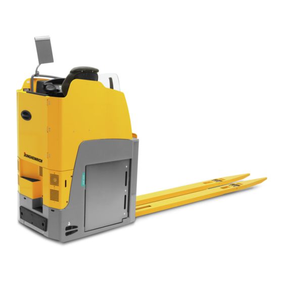
B Truck Description Application The ESE 533 is a four-wheel, electric side-seated pallet truck with two drive units and electrical steering with two steer motors. The truck is designed for transporting goods on level surfaces. It can lift open bottom or diagonal board pallets as well as roll cages beyond the area of the load wheels or roll cages. -
Page 12: Travel Direction Definition
Travel direction definition The following determinations have been made for travel direction specification: Item Travel Direction Left Drive direction Load direction Right... -
Page 13: Assemblies And Functional Description
Assemblies and Functional Description Assembly Overview Item Component Item Component t Steering wheel Option bar t Display unit Accelerator pedal t Key switch Brake pedal t Emergency Disconnect Driver's seat switch t Solopilot Drive wheel t Fork t Standard equipment Optional equipment... -
Page 14: Functional Description
Functional Description Safety Mechanisms Enclosed, smooth truck geometry. The wheels are surrounded by a solid skirt. The key switch (7) or Emergency Disconnect switch (8) disconnects all electrical function in hazardous situations. Travelling is inhibited if the driver door is not closed. Truck design The pallet truck has four wheels including two steered drive wheels (15). - Page 15 Controls and displays Controls and displays are clearly arranged in the operator position. The controls on soloPILOT (9) enable the travel direction, lifting/lowering and the horn to be controlled with one hand. Display unit (6) with large LC display as well as integrated hour meter, battery discharge indicator with lift cut-off function and speed display.
- Page 16 Emergency Stop safety feature The emergency stop is controlled by the traction controllers. The steering controllers send a system status signal which is monitored by the traction controllers. If the signal fails to appear or a fault is identified the truck automatically brakes to a halt. Control displays on the driver’s display indicate the emergency stop.
-
Page 17: Technical Specifications
Technical Specifications The technical specification is given according to the German guideline "Type sheets for industrial trucks". Technical modifications and additions reserved. Performance data Description ESE 533 Rated capacity 3300 Travel speed 19 / 20 km/h w / w.o. rated load Lift speed 5.6 / 6.0... -
Page 18: Dimensions
Dimensions Description ESE 533 Load centre distance with standard 1800 fork length (3600 mm) Load distance (lowered / raised) 2680 / 2630 Wheel base (lowered / raised) 3770 / 3720 Lift Seat height / standing height 1470 h13 Lowered fork height... -
Page 20: Weights
Weights Component ESE 533 Net weight (including battery) 3480 Axle load, w. load front/rear 3460 / 3320 (incl. battery) Axle load, w.o. load front/rear 2750 / 730 (incl. battery) Battery weight 1450 Tyre type Description ESE 533 Tyres (full rubber, super elastic,... -
Page 21: Norms
EN norms Continuous sound pressure level – ESE 533: 75 dB(A) in accordance with EN 12053 as harmonised with ISO 4871. The continuous sound pressure level is calculated according to standard procedures and takes into account the sound pressure level when travelling, lifting and idling. -
Page 22: Conditions Of Use
Conditions of use Ambient temperature – operating at 5°C to 40°C Special equipment and authorisation are required if the truck is to be used continually in conditions of extreme temperature or condensing air humidity fluctuations. Electrical Requirements The manufacturer certifies compliance with the requirements for the design and manufacture of electrical equipment, according to EN 1175 "Industrial Truck Safety - Electrical Requirements", provided the truck is used according to its purpose. -
Page 23: Identification Points And Data Plates
Identification points and data plates Indication Points Item Component Floor plate adjustment Strap point for crane lifting "Cold store" plate (cold store trucks only) o “Risk of trapping” label Seat belt Read operating instructions Capacity Qmax... - Page 24 Item Component Truck data plate Final inspection Company name Test plaque...
-
Page 25: Data Plate
Data plate The illustration shows the standard version for EU member states. The data plate may differ in other countries. Item Model Item Model Rated capacity (kg) Load centre distance (mm) Battery voltage (V) Drive output Net weight w.o. battery (kg) Min./max. -
Page 26: Stability
Stability The truck's stability has been tested according to latest technological standards. These take into account the dynamic and static tipover forces that can occur if used correctly. – Tyre type – Attachment – Transported load (size, weight and centre of gravity) Changing the components can alter the stability. -
Page 27: C Transport And Commissioning
C Transport and Commissioning Lifting by crane WARNING! Improper loading by crane can result in accidents Improper use or use of unsuitable lifting gear can cause the truck to crash when being loaded by crane. Prevent the truck from hitting other objects during lifting, and avoid uncontrolled movements. - Page 28 Lifting the truck by crane Requirements – Truck parked securely, see page 58. Tools and Material Required – Two ring screws, for capacity details refer to the truck data plate. – Crane slings, for capacity details refer to the truck data plate. Procedure •...
-
Page 29: Securing The Truck During Transport
Securing the truck during transport WARNING! Accidental movement during transport Improper fastening of the truck and mast during transport can result in serious accidents. uLoading must only be performed by specialist personnel trained for this purpose. The specialist personnel must be instructed in securing loads on road vehicles and handling load securing devices. - Page 30 Procedure • Position the wooden beam or pallet between the front of the transport vehicle and the load handler to ensure a positive fit between the front of the transport vehicle and the load handler. • Lay the lashing straps (43) over the truck, attach to the transport vehicle and tension sufficiently.
-
Page 31: Using The Truck For The First Time
Using the Truck for the First Time WARNING! The use of unsuitable energy sources can be hazardous Rectified AC current will damage the assemblies (controllers, sensors, motors etc.) of the electronic system. Unsuitable cable connections (too long, insufficient wire cross-section) to the battery (tow cables) can overheat, setting the truck and battery on fire. -
Page 33: D Battery - Servicing, Recharging, Replacement
D Battery - Servicing, Recharging, Replacement Safety instructions for handling lead-acid batteries Maintenance personnel Batteries may only be charged, serviced or replaced by trained personnel. These operating instructions and the manufacturer’s instructions concerning batteries and charging stations must be observed when carrying out the work. Fire protection measures WARNING! Short circuits can result in fire... -
Page 34: General Notes On Handling Batteries
The use of unsuitable batteries that have not been approved for the truck by Jungheinrich, can lead to a deterioration of the braking characteristics of the truck during energy recovery, causing considerable damage to the electric controller and resulting in serious danger to the health and safety of individuals. -
Page 35: Battery Types
Battery types The truck will be equipped with different battery models, depending on the application. The following table shows which combinations are included as standard: Component Capacity 10 PzB1000 48 V / 1000 Ah The battery weight can be taken from the battery data plate. Batteries with non insulated terminals must be covered with a non slip insulating mat. -
Page 36: Battery Removal And Installation
Battery removal and installation WARNING! Accident risk during battery removal and installation Due to the battery weight and acid there is a risk of trapping or scalding when the battery is removed and installed. uNote the "Safety regulations for handling acid batteries" section in this chapter. uWear safety shoes when removing and installing the battery. - Page 37 • Release the M12 pressure screws (44) from between the battery tray (50) and load section on either side of the truck. The screws secure the battery tray along the travel direction and prevent slipping. • Drive the cantilevered truck up to the side of the battery tray (50).
- Page 38 Removing and installing the battery with a battery roller stand Requirements – Park the truck securely, see page 58. – Battery disconnected. Tools and Material Required – Cantilevered truck, hand pallet truck (capacity min. 1.8 t) – Square key – M10 spanner –...
- Page 39 • Adjust the height of the battery roller stand. To do this, • release the counternuts (52) on the four feet (54). • Turn the adjusting spindle (51) with the square key until the precise transfer height reached. Repeat this for each foot.
-
Page 40: Charging The Battery
Charging the battery WARNING! The gases produced during charging can cause explosions The battery produces a mixture of nitrogen and hydrogen (electrolytic gas) during charging. Gassing is a chemical process. This gas mixture is highly explosive and must not be ignited. uSwitch the charging station and truck off first before connecting/disconnecting the charging cable of the battery charging station to/from the battery connector. -
Page 41: E Operation
E Operation Safety Regulations for the Operation of Forklift Trucks Driver authorisation The truck may only be used by suitably trained personnel, who have demonstrated to the proprietor or his representative that they can drive and handle loads and have been authorised to operate the truck by the proprietor or his representative. - Page 42 Hazardous area WARNING! Risk of accidents/injury in the hazardous area of the truck A hazardous area is defined as the area in which people are at risk due to travel or lifting operations of the truck, its load handler or the load. This also includes the area within reach of falling loads or lowering/falling operating equipment.
-
Page 43: Displays And Controls
Displays and Controls... - Page 44 Item Control / Display Function t Steers the truck. Steering wheel (optionally attached to the door) t Displays key travel and lift parameters, Display and control unit warnings, notification of incorrect operation and service displays t Switches the truck on and off. Key switch t Disconnects the power supply.
-
Page 45: Display Unit
Display unit Description The driver’s display unit represents the operator-truck interface. It is both a display and control module for the operator and the service engineer. Adjustments to the truck can be made by pressing the four short stroke keys (83, 84, 85, 86). - Page 46 Item Component Operation Stop sign display Red icon lights up when faults occur Parking brake display Icon lights up when the parking brake is applied or if the truck has been switched on. Warning symbol Icon lights up in connection with warning and error display messages (80) Steer angle...
- Page 47 Setting the time (73) Procedure • Press the Shift button (85) for 8 sec. until the “Set time” menu is displayed. • Set the hours with the Up (83) and Down (84) buttons. • Confirm with the Shift button (85). •...
- Page 48 2.1.1 Battery discharge indicator The battery charge status is shown on the truck display via a battery symbol (74). When a battery is discharged to the permissible discharge level, the battery symbol (74) is displayed empty. The standard setting for the battery discharge indicator (75) is based on standard batteries.
-
Page 49: Preparing The Truck For Operation
Preparing the Truck for Operation Checks and operations to be performed before starting daily operation WARNING! Damage and other truck or attachment (optional equipment) defects can result in accidents. If damage or other truck or attachment (optional equipment) defects are discovered during the following checks, the truck must be taken out of service until it has been repaired. -
Page 50: Entry And Exit
Entry and exit Entry and exit Procedure • Open the cab door (90). • From the outside: Pull the door handle (89). • From the inside: Apply the door lock lever (87) and open the door. • To enter and exit the cab, hold onto the handles (88). •... -
Page 51: Setting Up The Operator Position
Setting up the operator position WARNING! Accident risk uDo not adjust the driver’s seat, steering column or armrest during operation. Before starting to travel, adjust the driver’s seat, steering column and armrest (if necessary) so that all the controls are within reach and can be applied without having to strain. - Page 52 Adjusting the seat position CAUTION! An unsecured driver's seat can cause injury An unsecured driver's seat can slide out of its guide during travel, resulting in accidents. uThe driver's seat must be locked in position. uDo not adjust the driver’s seat while travelling. Procedure •...
- Page 53 3.3.2 Seat Belt WARNING! Travelling without a seat belt increases the risk of injury. Accidents or personal injury can result if the seat belt is not worn or is modified. uAlways put the seat belt on before starting the industrial truck. uDo not modify the seat belt.
- Page 54 3.3.3 Adjusting the steering column Adjusting the steering column Procedure • Release the steering column stop (96). • Position the steering head (97). • Fix the steering column stop (96) in position. The steering column is now positioned. 3.3.4 Adjusting the armrest with soloPILOT The armrest control unit with soloPILOT can be lengthways adjusted incrementally.
- Page 55 3.3.5 Adjustable footplate The truck is equipped with an infinitely adjustable footplate. Adjusting the footplate Procedure • Press and hold down on the footplate unlocking button (100). • Apply pressure to the footplate (101) to tilt it down. • Relieve the pressure from the footplate to tilt it up.
-
Page 56: Preparing The Truck For Operation
Preparing the truck for operation Switching on the Industrial Truck Requirements – For checks and operations to be performed before starting daily operation, see page 49. Procedure • Sit on the driver's seat. • Close the door. Because of the seat and door switch function the truck can only be operated when the seat is occupied and the door closed. -
Page 57: Checks And Operations To Be Carried Out When The Truck Is Operational
Checks and operations to be carried out when the truck is operational WARNING! Risk of accident due to damage to or other defects in the truck and optional features If damage or other truck or attachment (optional equipment) defects are discovered during the following checks, the truck must be taken out of service until it has been repaired. -
Page 58: Parking The Truck Securely
Parking the truck securely WARNING! An unsecured truck can cause accidents Parking the truck on an incline, without the brakes applied or with a raised load or load handler is dangerous and is strictly prohibited. uPark the truck on a level surface. In special cases the truck may need to be secured with wedges. -
Page 59: Industrial Truck Operation
Industrial Truck Operation Safety regulations for truck operation Travel routes and work areas Only use lanes and routes specifically designated for truck traffic. Unauthorised third parties must stay away from work areas. Loads must only be stored in places specially designated for this purpose. The truck must only be operated in work areas with sufficient lighting to avoid danger to personnel and materials. - Page 60 Negotiating lifts, loading ramps and docks Lifts may only be negotiated if they have sufficient capacity, are suitable for driving on and authorised for truck traffic by the owner. The driver must satisfy himself of the above before entering these areas. The truck must enter lifts with the load in front and must take up a position which does not allow it to come into contact with the walls of the lift shaft.
-
Page 61: Emergency Disconnect
Emergency Disconnect CAUTION! Applying maximum braking can result in accidents Applying the Emergency Disconnect switch during travel will cause the truck to decelerate to a halt at maximum force. This may cause the load to slide off the load handler. There is a higher risk of accidents and injury. uDo not use the Emergency Disconnect switch as a service brake. - Page 62 Pressing the emergency disconnect switch Procedure • Press the emergency disconnect switch (106). All electrical functions are deactivated. The truck brakes to a halt. Press the Emergency Disconnect switch on in emergencies. Releasing the emergency disconnect switch Procedure • Turn the emergency disconnect switch (106) to unlock it. All electrical functions are enabled and the truck is operational again (provided the truck was operational before the emergency disconnect switch was pressed).
-
Page 63: Travel
Travel WARNING! Improper travel can result in accidents uDo not get up from the driver’s seat during travel. uDo not drive the truck unless the panels are closed and properly locked. - Page 64 Travel Requirements – Truck prepared for operation, see page 56. Procedure • Sit on the driver's seat. • Close the truck door. Because of the seat and door switch function the truck can only be operated when the seat is occupied and the door closed. •...
-
Page 65: Brakes
Brakes The truck can brake in three different ways: – Service brake – Inversion brake – Coasting brake WARNING! Accident risk The brake pattern of the truck depends largely on the ground conditions. uThe driver must be aware of travel route conditions and them into account when braking. - Page 66 Braking with the service brake Procedure • Depress the brake pedal (13) until you feel the brake pressure. The truck decelerates depending on the brake pedal position. Braking with the reversing brake Procedure • Set the travel direction switch (61) to the opposite direction while travelling. The truck decelerates until it starts to travel in the opposite direction.
-
Page 67: Steering
Steering Steering mode type The ESE 533 has 360° endless steering. In this mode the steering angle of the wheels is endless and can therefore be used to reverse the travel direction. DANGER! Excess speed around bends can result in accidents uAlways negotiate bends at slow speed. -
Page 68: Lifting, Transporting And Depositing Loads
Lifting, transporting and depositing loads Picking up load units Requirements – Load unit correctly palletised. – Load weight matches the truck's capacity. – Distribute loads evenly on the fork arms. Procedure • Drive the truck slowly up to the pallet. •... - Page 69 Transporting load units Requirements – Good ground conditions. Procedure • Accelerate gradually. • Travel at a constant speed. • Transport the load unit as low as possible above the ground outside the rack aisle. Check the ground clearance. Setting down the load Requirements –...
-
Page 70: Operating The Truck Without Its Own Drive System
Operating the truck without its own drive system WARNING! Accidental truck movement When the brakes are de-activated the truck must be parked on a level surface, since the brakes are no longer effective. uDo not release the brake on slopes or inclines. uDo not park the truck with the brake released. - Page 71 Operating the truck without its own drive system Requirements – Truck prepared to be moved without its own drive system.
- Page 72 Procedure • Release the magnetic brakes. To do this: • Disconnect the two-pin connector from both magnetic brakes. • Screw the screws (2 x M5) into the holes (109) on the magnetic brakes. Before recovering the truck, the drive wheels can be turned to the required position via the centre screw of the steering motors using a steering crank (110).
- Page 73 Park the truck securely at its destination. Procedure • Place the protective cap over the centre screws of the two drive motors. • Remove the screws (2 x M5) from the magnetic brakes. • Connect both magnetic brakes to four-pin connectors. •...
-
Page 74: Troubleshooting
Troubleshooting This chapter allows the user to identify and rectify basic faults or the effects of incorrect operation. When trying to locate a fault, proceed in the order shown in the table. If the fault cannot be rectified after carrying out the above procedures, notify the manufacturer’s service department, as further troubleshooting can only be performed by specially trained and qualified service personnel. -
Page 75: Truck Does Not Start
Truck does not start Possible Cause Action Battery connector not plugged in Check the battery connector and plug it in if necessary. Emergency Disconnect pressed. Unlock the Emergency Disconnect Key switch set to O. Set the key switch to “I” Battery charge too low Check the battery charge and charge battery if necessary. -
Page 76: Optional Equipment
Optional equipment Keypad (CanCode) (o) 7.1.1 Code lock The code lock allows a user or group of users to assign an individual user code. Travel programs can also be assigned to the individual user codes. The user code is configured with a master code and is described in the following sections in this chapter. - Page 77 The keypad consists of 10 digit keys, a Set key (114) and a o key (116). Digit keys The digit keys are used to enter the user or master code and select the travel program. The green LEDs of the digit keys 1, 2 and 3 (111, 112, 113) show the travel program setting.
- Page 78 7.1.2 Preparing the truck for operation with the keypad (CanCode) Preparing the truck for operation by entering a valid operator code Procedure • Pull the Emergency Disconnect to unlock it, see page 61. The LED (115) lights up red. • Enter the operator code with the digit keys. When you have entered a valid operator code the LED (115) lights up green, the travel program selected is indicated by the corresponding LEDs (111,112,113) and the truck is switched on.
- Page 79 7.1.4 Changing the Set-up Code To change the length of the master code you must follow the procedure in "Choose length of the new master code (4-6 digit) and add user codes", see page 88. If there are still user codes stored in the code lock, the master code to be changed must be the same length as the saved user codes.
- Page 80 Error displays changing the master code For the following events the LED (115) flashes red: Cause Remedy – Switch off the truck, see page 78. – Choose a different master code, see page 79. – New master code is already –...
- Page 81 7.1.5 Add operator code Requirements – To prepare the truck for operation, see page 78. Procedure • Press the O key (116). • Enter the valid master code with the digit keys. When you enter the valid master code the LED (115) flashes green.
- Page 82 Error displays adding a user code For the following events the LED (115) flashes red: Cause Remedy – The user code entered is – Switch off the truck, see page 78. not the same length as the – Repeat the entry, making sure that the master master code code is the same length as the user code.
- Page 83 7.1.6 Change operator code Requirements – To prepare the truck for operation, see page 78. Procedure • Press the O key (116). • Enter the valid master code with the digit keys. When you enter the valid master code the LED (115) flashes green.
- Page 84 Error displays changing a user code For the following events the LED (115) flashes red: Cause Remedy – The user code entered is – Switch off the truck, see page 78. not the same length as the – Repeat the entry, making sure that the master master code code is the same length as the user code.
- Page 85 7.1.7 Delete individual user codes Requirements – To prepare the truck for operation, see page 78. Procedure • Press the O key (116). • Enter the valid master code with the digit keys. When you enter the valid master code the LED (115) flashes green.
- Page 86 Error displays deleting individual user codes For the following events the LED (115) flashes red: Cause Remedy – The user code entered is – Switch off the truck, see page 78. not the same length as the – Repeat the entry, making sure that the master master code code is the same length as the user code.
- Page 87 7.1.8 Delete all user codes, Requirements – To prepare the truck for operation, see page 78. Procedure • Press the O key (116). • Enter the valid master code with the digit keys. When you enter the valid master code the LED (115) flashes green.
- Page 88 7.1.9 Choose length of the new master code (4-6 digit) and add user codes The master code is factory set to a four-digit entry: If necessary, the four-digit master code can be changed to a five or six-digit entry. Before the master code length can be changed, all user codes must be deleted.
- Page 89 7.1.10 Setting the automatic truck cutout (timeframe) Requirements – To prepare the truck for operation, see page 78. Procedure • Press the O key (116). • Enter the valid master code with the digit keys. When you enter the correct master code the LED (115) flashes green.
- Page 90 Error displays setting the automatic cutout period of the truck For the following events the LED (115) flashes red: Cause Remedy – Switch off the truck, see page 78. – Cutout time entered is out of – Enter the time again while making sure it is range within range.
- Page 91 7.1.11 Assigning the travel program The travel programs are fixed to the user code and can be released or blocked with a configuration code. The configuration code can also be used to assign a starting travel program to each user code. The starting travel program is the travel program that is activated when the truck is switched on and is displayed by the (111,112,113) LEDs.
- Page 92 Specifying a configuration code: Setting Description – Travel program 1 is blocked for the user code selected 1st digit – Travel program 1 is enabled for the user code selected – Travel program 2 is blocked for the user code selected 2nd digit –...
- Page 93 Adapting the travel program configuration to the user code Procedure • Press the O key (116). • Enter the valid master code with the digit keys. When you enter the valid master code the green LED (115) flashes green. • Enter the parameters 0-2-4 with the digit keys. •...
- Page 94 Error displays configuring the travel programs For the following events the LED (115) flashes red: Cause Remedy – Blocked travel program – Switch off the truck, see page 78. defined as start travel – Try again, making sure the configuration code is program entered correctly.
-
Page 95: Floor-Spot
Floor-Spot The floor spot serves as an auxiliary device and projects a coloured dot onto the ground. CAUTION! Risk of accident due to restricted view Looking directly at the LED light can dazzle and temporarily impair eyesight. uDo not look directly at the LED light. uPractise travelling and working with the floor spot carefully. - Page 96 7.2.1 Additional information on Floor-Spot blue CAUTION! Risk of retinal damage due to blue light The Floor-Spot on the truck is classified in risk group 2 according to the standard IEC 62471: medium risk. In the range of 400 nm to 780 nm, blue light can potentially damage the retina of the human eye.
-
Page 97: F Industrial Truck Maintenance
The manufacturer cannot be held liable for damage caused by the use of non-original spare parts. product-related electronic spare parts catalogue found (www.jungheinrich.de/spare-parts-search) by entering the serial number. The serial number can be found on the data plate, see page 25. -
Page 98: Operational Safety And Environmental Protection
Operational Safety and Environmental Protection The inspections and maintenance tasks listed in chapter "Maintenance, Inspection and Changing of Maintenance Parts Requiring Replacement" must be performed according to the defined service intervals (see page 125). The manufacturer recommends the replacement of the maintenance parts also listed in chapter "Maintenance, Inspection and Changing of Maintenance Parts Requiring Replacement"... -
Page 99: Maintenance Safety Regulations
Maintenance Safety Regulations Maintenance and repair personnel The manufacturer has a customer service department specially trained for these tasks. A maintenance contract with the manufacturer will support trouble-free operation. Truck maintenance, repair work and changing of parts requiring replacement must only be carried out by specialist personnel. -
Page 100: Wheels
Wheels WARNING! The use of wheels that do not match the manufacturer's specifications can result in accidents The quality of wheels affects the stability and performance of the truck. Uneven wear reduces truck stability and increases the stopping distance. uAfter replacing wheels, make sure the truck is not skewed. uAlways replace wheels in pairs, i.e. -
Page 101: Hydraulic System
Hydraulic system NOTICE Checking and replacing hydraulic hoses Hydraulic hoses can become brittle through age and must be checked at regular intervals. The application conditions of the industrial truck have a considerable impact on the ageing of the hydraulic hoses. uCheck the hydraulic hoses at least once per year and replace if necessary. -
Page 102: Lubricants And Lubrication Schedule
Lubricants and Lubrication Schedule Handling consumables safely Handling consumables Consumables must always be handled correctly. Follow the manufacturer’s instructions. WARNING! Improper handling is hazardous to health, life and the environment Consumables can be flammable. uKeep consumables away from hot components and naked flames. uAlways keep consumables in prescribed marked containers. - Page 103 CAUTION! Consumables and used parts are an environmental hazard Used parts and consumables must be disposed of in accordance with the applicable environmental-protection regulations. Oil changes should be carried out by the manufacturer's customer service department, whose staff are specially trained for this task.
-
Page 104: Lubrication Schedule
Lubrication Schedule Lubrication schedule valid from 08.2015 (A + C)k 0,7 l 2,9 l k(B+C) g Contact surfaces k Cold Store Application b Transmission oil filler neck Grease nipple a Transmission oil drain plug Hydraulic oil filler neck Compound ratio for cold store usage 1:1... - Page 105 Lubrication schedule valid from 09.2015 (A + C)k 0,7 l 2,9 l k(B+C) g Contact surfaces k Cold Store Application b Transmission oil filler neck Grease nipple a Transmission oil drain plug Hydraulic oil filler neck Compound ratio for cold store usage 1:1...
-
Page 106: Consumables
The Jungheinrich hydraulic oil is available only from the Jungheinrich service department. The use of named alternative hydraulic oils is not prohibited, but may lead to a decline in functionality. The Jungheinrich hydraulic oil may be mixed with one of the named alternative hydraulic oils. -
Page 107: Maintenance And Repairs
Maintenance and repairs Preparing the truck for maintenance and repairs Procedure • Park the truck securely, see page 58. • Disconnect the battery to prevent the truck from being switched on accidentally. Lifting and jacking up the truck safely WARNING! Lifting and jacking up the truck safely In order to raise the truck, the lifting gear must only be secured to the points specially provided for this purpose. -
Page 108: Cleaning
Cleaning 5.3.1 Cleaning the truck Cleaning tasks may only take place in the designated locations, which adhere to the stipulations of the country of use. CAUTION! Fire hazard Do not use flammable liquids to clean the industrial truck. uDisconnect the battery before starting cleaning work. uCarry out all necessary safety measures to prevent sparking before cleaning (e.g. - Page 109 Requirements – Truck prepared for maintenance and repair work (see page 107). Tools and Material Required – Water-based solvents – Sponge or cloth Procedure • Clean the surface of the truck with water-based solvents and water. Use a sponge or cloth to clean. •...
- Page 110 5.3.2 Cleaning the electrical system assemblies CAUTION! Risk of electrical system damage Cleaning the assemblies (controllers, sensors, motors etc.) of the electronic system with water can damage the electrical system. uDo not clean the electrical system with water. uClean the electrical system with weak suction or compressed air (use a compressor with a water trap) and not a conductive, anti-static brush.
-
Page 111: Drive Compartment Cover Disassembly/Assembly
Drive compartment cover disassembly/assembly Remove drive compartment cover Requirements – Prepare the truck for maintenance and repairs (see page 107). Tools and Material Required – Allen key Procedure Hold onto the cover (118) when removing the screws. Remove the four screws (119) with the Allen key. -
Page 112: Checking The Hydraulic Oil Level
Checking the hydraulic oil level NOTICE There are markings on the hydraulic reservoir. Always check the hydraulic oil level when the load handler is lowered. - Page 113 Checking the hydraulic oil level and topping up the hydraulic oil Requirements – Fully lower the load handler. – Prepare the truck for maintenance and repair work, see page 107. Procedure • Remove screws (120) from the cover (121). • Remove the cover (121) from the hydraulic reservoir. •...
-
Page 114: Checking Electrical Fuses
Checking electrical fuses Check fuses Requirements – Truck prepared for maintenance and repairs Procedure • Pull the dashboard panel up. • Open and remove the fuse box. • Check the fuse ratings against the table and replace if necessary. • Close the fuse box. •... - Page 115 138 139 140 141...
-
Page 116: Checking The Wheel Attachments
Checking the wheel attachments. Tightening Torques Load wheels (1x countersunk bolt per 84 Nm load wheel) Drive wheel 195-10 Nm Checking the wheel attachment Requirements – Truck prepared for maintenance and repairs, see page 107. Tools and Material Required – Torque wrench for M14 hex. wheel bolts and M12 hex / rounded hex. - Page 117 Procedure • Align the drive wheels via the steering drive so that the wheel bolts can be accessed through the side recesses in the truck frame. To ensure that all bolts can be accessed, the wheels must be turned in stages. •...
-
Page 118: Restoring The Truck To Service After Maintenance And Repairs
Restoring the truck to service after maintenance and repairs Procedure • Attach the battery connector (147) to the industrial truck. • Preparing the truck for operation, see page 49. • Prepare the truck for operation, see page 56. • Test the safety mechanisms, see page 57. -
Page 119: Decommissioning The Industrial Truck
Decommissioning the industrial truck If the truck is to be out of service for more than a month, it must be stored in a frost- free and dry room. All necessary measures must be taken before, during and after decommissioning as described hereafter. When the truck is out of service it must be jacked up so that all the wheels are clear of the ground. -
Page 120: Prior To Decommissioning
Prior to decommissioning Procedure • Thoroughly clean the truck – see page 102. • Prevent the truck from rolling away accidentally. • Check the hydraulic oil level and replenish if necessary, see page 104. • Apply a thin layer of oil or grease to any non-painted mechanical components. •... -
Page 121: Restoring The Truck To Service After Decommissioning
Restoring the truck to service after decommissioning Procedure • Thoroughly clean the truck – see page 104. • Lubricate the forklift truck according to the lubrication schedule – see page 40. • Equipped with lead-acid battery (t): Clean the battery, grease the battery terminal screws with terminal grease and connect the battery. -
Page 122: Safety Tests To Be Performed At Intervals And After Unusual Incidents
Safety tests to be performed at intervals and after unusual incidents The truck must be inspected at least annually (refer to national regulations) or after any unusual event by a qualified inspector. The manufacturer offers a safety inspection service which is performed by personnel specifically trained for this purpose. -
Page 123: Final De-Commissioning, Disposal
Final de-commissioning, disposal Final de-commissioning or disposal of the truck in must be performed in accordance with the regulations of the country of use. In particular, regulations governing the disposal of batteries, consumables and electronic and electrical systems must be observed. -
Page 125: Maintenance, Inspection And Changing Of Maintenance Parts Requiring Replacement
G Maintenance, Inspection and Changing of Maintenance Parts Requiring Replacement WARNING! Lack of maintenance can result in accidents Failure to perform regular maintenance and inspections can lead to truck failure and poses a potential hazard to personnel and equipment. uThorough and expert maintenance and inspections are among the most important requirements for the safe operation of the industrial truck. -
Page 126: Maintenance Contents Ese
Maintenance Contents ESE 533 Issued on: 2021-02-17 12:00 Owner To be performed every 50 service hours, but at least once a week. 1.1.1 Maintenance contents 1.1.1.1 Standard equipment Brakes Test the brake. Hydraulic operations Correct the hydraulic-oil level. 1.1.1.2 Optional equipment... - Page 127 Chassis/structure Industrial truck for damage and leaks Check labels for legibility, completeness and plausibility Check doors or covers for damage Hydraulic operations Test hydraulic system Check fork arms or load handler for wear and damage 1.1.2.2 Optional equipment The following points must be checked: Cold store cabin Chassis/structure Roof hatch for functionality and damage...
-
Page 128: Customer Service
Customer Service In accordance with the ESE 533 service interval, to be performed every 1000 service hours, but at least once a year. 1.2.1 Maintenance contents 1.2.1.1 Standard equipment Brakes Test the brake. Adjust the air gap of the magnetic brake. - Page 129 1.2.1.2 Optional equipment Radio data System components Clean the scanner and terminal. Lead-acid battery, international Electrical system Carry out a frame leakage test. Power supply Clean the battery. Clean and grease the battery terminals. Measure acid density and battery voltage. Correct the battery-acid level using demineralised water.
- Page 130 Power supply Battery connector for secure fit, functionality and damage Travel Drive system bearings for wear and damage Transmission for noise and leaks Check wheels for wear, damage and secure mounting Check wheel bearings and mounting of wheels for wear and damage Chassis/structure Industrial truck for damage and leaks Check chassis connections and screw connections are securely attached and check for...
- Page 131 1.2.2.2 Optional equipment Cold store cabin Chassis/structure Roof hatch for functionality and damage Cold store cabin for secure fit and damage Windscreens for damage Test window heating and check for damage Test doors and check for damage Electrolyte recirculation Power supply Hose connections and pump for correct function Aquamatic Power supply...
- Page 132 Access module Electrical system Check access module is securely attached, test and check for damage Electrical heating Chassis/structure Test the heater Entry skids/rollers Hydraulic operations Check entry skids or entry rollers for damage and wear, and test their function Belt lock monitoring Chassis/structure Test seat belt monitoring and check for damage Discharge strap...
- Page 133 1.2.3.2 Optional equipment Cold store application maintenance part service hours months Transmission oil in cold store application Transmission oil additive Hydraulic oil Hydraulic oil additive...
Need help?
Do you have a question about the ESE 533 and is the answer not in the manual?
Questions and answers