
Summary of Contents for Fike FVA-IP
- Page 1 Fike Video Analytics® FVA‐IP Camera Installation and Operation Manual P/N: 06-523 Rev: 6, 06/19 Video Analytics Corporation FIKE VIDEO ANALYTICS CORPORATION...
- Page 2 DEVELOPED BY Fike Video Analytics Corporation 704 SW 10 Street Blue Springs, Missouri 64013‐0610 U.S.A. Phone: 844‐345‐3843 COPYRIGHT NOTICE Copyright 2014. All rights reserved. Fike Video Analytics Corporation copyrights this manual and products it describes. You may not reproduce, transmit, transcribe, or any part of this manual without express, written permission from Fike Video Analytics Corporation. This manual contains proprietary information intended for distribution to authorized persons or companies for the sole purpose of conducting business with Fike Video Analytics Corporation. If you distribute any information contained in this manual to unauthorized persons, you have violated all distributor agreements and we may take legal action. TRADEMARKS Fike Video Analytics Corporation is a registered trademark of Fike Corporation. ...
-
Page 3: Table Of Contents
Appendix A – FVA-IP Camera Specifications ......................35 Appendix B - Dry Contact Diagram ..........................39 Appendix C – Fike Video Analytics System FM approved Computer Requirements ..........41 Appendix D - Commissioning Paper Work ......................... 43 ... - Page 4 Installation and Operation Manual FVA-IP Camera This page intentionally left blank. P/N 06-523 (Rev. 6) Revision Date: June, 2019...
- Page 5 FVA-IP Camera Installation and Operation Manual IMPORTANT SAFETY INSTRUCTIONS 1. Read these instructions. Keep these instructions 2. Head all warnings. Follow all instructions 3. Do not use this camera near water. Clean only with dry cloth. 4. Install in accordance to the manufacturer’s instructions 5. Do not install near heat sources such as radiators, heat registers, stoves, or other apparatus (including amplifiers) that produce heat. 6. Only use attachments / accessories specified by the manufacturer. 7. Refer all servicing to qualified service personnel. Servicing is required when the camera has been damaged in anyway. 8. WARNING: To reduce the risk of fire or electric shock, do not expose this camera to rain or moisture. 9. Installation should be done only by qualified service personnel and conform to local codes. 10. Ensure that the camera is securely mounted. Use installation methods and materials capable of supporting four times the maximum specified load. 11. Only power with 12‐24 VDC (UL), 12 VDC (FM) from UL listed Class 2 power supply for security or fire should be used. POE may be used as supplemental to the listed 12 or 24 volt power supply. 12. Please thoroughly familiarize yourself with the information in this manual prior to installation and operation. 13. This device complies with part 15 of the FCC Rules. Operation is subject to the following two conditions: (1) ...
-
Page 6: Introduction To Fike Video Analytics
‐‐ to detect anomalies characteristic of smoke, fire and motion. With the Fike Video Analytics video management software user interface, Fike Video Analytics early fire and smoke detection capability is unmatched by any traditional smoke detection technology. Fike Video Analytics, located within a Texas Instruments chip onboard the FVA‐IP camera, can detect a flaming fire in a 7 by 7 pixel area, as well as both ambient and plume like smoke patterns. The Fike Video Analytics system is also capable of detecting reflected fire light off walls or objects so that a fire can be detected even if the flames are not in the camera’s line of sight. ... -
Page 7: Video Management Software User Interface
FVA-IP Camera Installation and Operation Manual 1.2 Video Management Software User Interface With Fike Video Analytics video management software user interface, you can use an approved workstation for video surveillance, fire safety monitoring, and to configure any number of cameras. The software provides the tools to monitor your facilities, build an organization tree and import plant site drawings, building schematics, and photos. ... -
Page 8: Scalable System Architecture
1.3 Scalable System Architecture A Fike Video Analytics system is comprised of at least one FVA‐IP camera, a video management system, and the monitoring solution. You can connect any number of FVA‐IP cameras and network recorders via standard LAN / Ethernet network to expand the system to meet end user needs (limit of 32 cameras per network recorder). FVA‐IP ... -
Page 9: Fike Video Analytics System Design
FVA-IP Camera Installation and Operation Manual 2.0 Fike Video Analytics System Design The system design should include the proper coverage of the hazard area as well as monitoring of the events recorded by the FVA‐IP cameras. The monitoring can be done by on‐site security or a remote monitoring facility. The system architecture is very flexible to suit the end users needs and care should be taken when designing the system layout to meet the needs of the end user. Some examples of the varying architectures include: Wiring the cameras directly to the dry contacts of a FM approved FACP Connecting the cameras to on‐site monitoring using the coax or the LAN connection Configuring the cameras to be remotely monitored by a third party or corporate site Using a video management system to record events for post event analysis Any combination of architecture can be combined to produce the desired results. 2.1 System Design NOTE: All the requirements of NFPA 72, including but not limited to, back‐up power requirements, maintenance requirements, and performance‐based installation criteria should be followed. NOTE: Power with 12‐24 VDC (UL), 12 VDC (FM) from UL listed Class 2 power supply for security or fire should be used. POE may be used as supplemental to the listed 12 or 24 volt power supply. The FVA‐IP camera should be connected to either Power‐Over‐Ethernet (POE) or a 12/24 VDC 1A, Class 2 power supply certified for use with security and or fire applications only. Both can be used together for redundancy. Electrical ratings can be found on the FVA‐IP cameras. If you are unsure of camera placement, you may want to perform a Fire Hazard Analysis (FHA) and or a performance‐based design analysis to determine the proper placement and number of cameras to adequately protect the area. It is important to consider the desired performance and prevention of nuisance alarms. Take into account predicted smoke flow, ceiling obstructions, configuration of contents, lighting, and desired fire size at detection. The location and spacing of cameras should be the result of an engineering evaluation that includes: Size and type of fire to be detected ... -
Page 10: Field Of View (Fov)
Installation and Operation Manual FVA-IP Camera Cameras should be mounted high and away from interferences so they can overlook the area of protection. The camera should be mounted so that large sources of light (glass walls, large bay doors, or directional spot lights) will not compromise the image quality by saturating the image sensor with light. Ideally, the FOV will include both the ceiling and floor of the facility, as shown in the Figure 3 below. Fig 3 ‐ The camera is positioned high in the space and the FOV covers both the floor and ceiling, maximizing the area covered. The camera was mounted 15 ft. (4.6 m) high with a 70 ft. (21 m) unobstructed view down the length of the warehouse. 2.2 Field of View (FOV) The most significant factor affecting system performance is the camera positioning and the resulting FOV. It is ... -
Page 11: Detection Range
FVA-IP Camera Installation and Operation Manual Table 1 – Detection times in seconds of IP camera models to various sources. Distance to EX 8 mm Fuel Source 2.8 mm FOV 6 mm FOV 8 mm FOV detector FOV 1 ft pan of Heptane 100 ft 18 9 9 9 1 ft pan of JP‐8 100 ft 18 10 10 10 1 ft pan of Ethyl Alcohol 100 ft 21 10 11 11 1 ft pan of Isopropyl Alcohol 100 ft 16 9 9 10 1 ft pan of Unleaded Gasoline ... -
Page 12: Environmental Considerations
Installation and Operation Manual FVA-IP Camera 2.4 Environmental Considerations To maximize the fire detection potential of the Fike Video Analytics system, the camera lenses should be properly set up to ensure sharp images. Using a portable TV with the BNC connection attached to the back of the IP camera will allow localized adjustment to optimize the image focus. Lenses should be clean and free of scratches. Camera positioning should consider light saturation and consistency, mounting integrity, humidity, airborne particulates, and other potentially damaging ambient conditions. Bright light sources should be located behind the cameras. The area to be protected should be uniformly illuminated; fluctuations caused by natural light should be limited. ... -
Page 13: Powering Up The System
FVA-IP Camera Installation and Operation Manual 2.6 Powering Up the System The system and all its electrical components should be supplied with power from an uninterrupted power source. This will ensure that the cameras, guard station, and network will remain functioning over the course of power loss. The amp hour for the system to maintain power will vary depend on the number of cameras used. Calculations should be conducted to ensure adequate backup power is available to maintain the system for 24 hours. NOTE: Backup power supply for cameras should adhere to the requirements of NFPA 72 and be NRTL certified for fire. NOTE: Power with 12‐24 VDC (UL), 12 VDC (FM) from UL listed Class 2 power supply for security or fire should be used. POE may be used as supplemental to the listed 12 or 24 volt power supply. The voltage required to operate the camera is clearly marked on the rear panel of the camera. The green power LED on the rear and front of the IP camera indicates that power is connected. Power consumption is approximately 5.0 Watts. The IP Camera is fitted to automatically switch between low voltage power supply and POE if one is to fail. NOTE: All wiring should be done according to NEC 70 practices. 2.7 Network Configuration NOTE: If your organization uses static IP addresses (i.e. does not use DHCP services) you must provide specific IP ... -
Page 14: Typical Configurations
Network setup has been completed. Refer to section 3.5 for details. The typical Fike Video Analytics setup will be similar to the one shown in Figure 4 and includes the following components: FVA‐IP Camera(s) connected by CAT‐5 cable to a network hub or LAN, connecting the monitoring ... -
Page 15: Installation
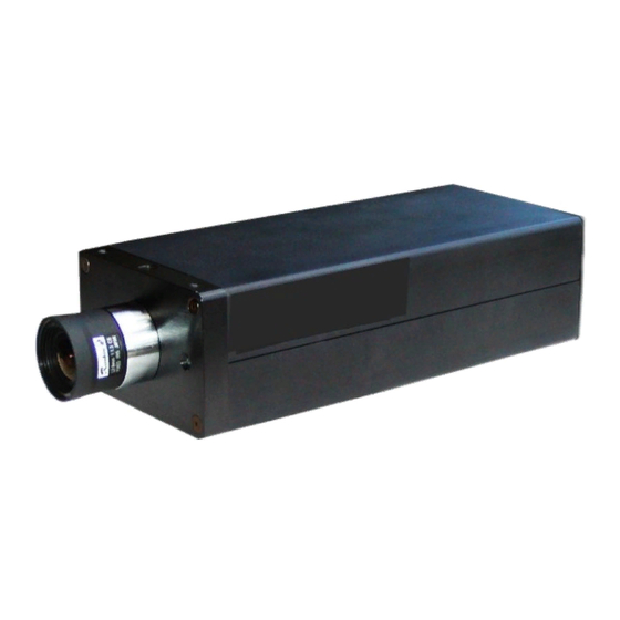
These records will be useful for regular system maintenance and any future incident investigation. NOTE: The Fike Video Analytics detection system shall comply with all applicable requirements of NFPA 72, including but not limited to, back‐up power requirements, maintenance requirements, and performance‐based installation criteria. NOTE: The system maintains a supplemental status to enhance fire detection and protection of assets and property. NOTE: Only personnel trained and certified to install the FVA‐IP Camera should install and commission a Fike Video Analytics system. Installation should be in accordance to the instructions within this manual and NFPA guidelines. 3.1 IP Camera Setup Once the camera locations have been selected, the entire procedure will consist of the following steps: ... - Page 16 Installation and Operation Manual FVA-IP Camera Pins 12-13 NOT used. Fig 5 – Back plane of the FVA‐IP camera showing the layout of the LED’s, and dry contact, Ethernet, BNC, power in, power out, and audio connections. Power with 12‐24 VDC (UL), 12 VDC (FM) from UL listed Class 2 power supply for security or fire should be used. POE may be used as supplemental to the listed 12 or 24 volt power supply. Fig 6 – Front Plane of the FVA‐IP camera showing location of the C/CS Lens mount and Front panel LED. Also the dimensions of the lens are shown. P/N 06-523 (Rev. 6) Revision Date: June, 2019...
-
Page 17: Power & Computer Connections
FVA-IP Camera Installation and Operation Manual There are three LED’s located on the FVA‐IP camera; front, right rear and left rear. The color of the pulse and the resulting state are listed in Table 4. The Front LED provides the alarm condition of the camera. The left rear LED ... - Page 18 Installation and Operation Manual FVA-IP Camera 4. Select Internet Protocol (TCP/IP) and click the Properties button. The Internet Protocol (TCP/IP) Properties dialog box opens at the General tab. 5. Select Use the following IP Address and enter the IP address in the correct range (192.168.0.1 to 192.168.0.256, subnet mask 255.255.255.0. 6. Connect the computer to a HUB and the IP camera to the same HUB using CAT‐5 cables. You are now ready to power up and connect to the IP Camera. Note the cameras by default are set to 192.168.0.100 so you cannot use this address for the NVR or you will create an IP address conflict. P/N 06-523 (Rev. 6) Revision Date: June, 2019...
-
Page 19: Ip Camera Communications
FVA-IP Camera Installation and Operation Manual Connect either an Ethernet CAT‐5 cable with POE, 12 or 24 VDC camera power supply to the appropriate power contacts on the rear of the FVA‐IP camera. NOTE: Power with 12‐24 VDC (UL), 12 VDC (FM) from UL listed Class 2 power supply for security or fire should be used. POE may be used as supplemental to the listed 12 or 24 volt power supply. Connect the Ethernet cable to a hub and attach the laptop or workstation used to configure the camera to the hub. FVA-IP Camera to be configured (192.168.0.100) 3.3 IP Camera Communications Open the preferred internet browser (FireFox or Internet Explorer) and type http://192.168.0.100/admin in the address bar. If the connection is successful you will be prompted for a user name and password, Figure 7. The factory default user name and password are admin and axonx, respectively. Fig 7 – Required user name (admin) and password (axonx) to establish connection to the FVA‐IP camera. Revision Date: June, 2019 P/N 06-523 (Rev. 5) - Page 20 Installation and Operation Manual FVA-IP Camera Once you have entered in the user name and password the Administration Home page will appear, Figure 8. You are now connected to the FVA‐IP camera and configuration of the setting can commence. The page is broken into two sections; one for an operator the other for the administrator. Although the operator features are present, it is suggested that all monitoring by the operator be done using the Fike Video Analytics video management software or the host fire alarm panel. Both sections, administrator and operator, are secured from the other by a user name and password. The factory default user name and password for each section is: Operator section: User Name: operator Password: axonx Administrator section User Name: admin Password: axonx These passwords can be changed by the administrator in the administration section under configure>access control. The operator has access to the camera status, live video, relay control and snap shot features. The administrator can configure the camera including schedules and zones, print a report of the configuration, as well as restart and update the FVA‐IP camera. Each of these features will be discussed in the following sections. Fig 8 – Administration Home page P/N 06-523 (Rev. 6) Revision Date: June, 2019...
-
Page 21: Operator Features
FVA-IP Camera Installation and Operation Manual 3.4 Operator Features The first feature on the operator list is the Camera Status, Figure 9. This table provides the operator the state of each alarm and trouble condition. It also allows the operator to switch the state and turn on any of the alarm or trouble states for testing purposes. Turning any of the states “on” results in an event file being created and recorded and any dry contacts that are set to close on the event type would close. This feature is good for testing the camera’s functionality or recording events that are non detectable by the analytics (i.e. fighting, theft, breach of protocol, etc.). The override will continue until the operator returns the function to off. Fig 9 – Camera algorithm status and override features The Live Video feature allows for the operator to view the video feed produced by the FVA‐IP camera. The video can be seen using the JAVA Applet or Multipart Stream (FireFox only), Figure 10. ... - Page 22 Installation and Operation Manual FVA-IP Camera Figure 11 displays the video feed from the camera using the JAVA Applet. By default the frame rate is set to two frames per second (fps). The frame rate is configurable to between 1 and 15 fps to limit bandwidth usage or provide a smother image feed, respectively. Once the desire frame rate is chosen click the update button and the video will run at the desired frame rate. Fig 11 – Live video from the camera at the default 2 fps. Returning to the Operations menu, Relay Control identifies the state of the relay, what event types are associated with a given relay, and provides the operator the functionality to confirm, delay, or reset an event, Figure 12. Each relay is configured with event types and can be given a count down to delay contact closer so onsite or remote monitoring personnel have time to see and confirm the event before action is taken by the camera. The monitoring personnel can then confirm the event which instantly closes the dry contact, delay the event which resets the count down, or reset the event which resets the background image and closes the event file. ...
-
Page 23: Administration Features
FVA-IP Camera Installation and Operation Manual The final feature available to the operator is a Snapshot feature which provides a current frame to the operator, Figure 13. Fig 13 – Snap shot taken from the camera. 3.5 Administration Features The administrator (a trained and certified authority having sole control of the settings) of the system has a number of features he/she should be familiar with and will have to configure to fit the architecture and design of the system. This includes the network configuration, sensitivity settings, relay closures, schedules, zones, and passwords. The first feature on the administrator menu is the configuration tab that contains a number of sub menu items, Figure 14. Fig 14 – Configure option under the administrator section has a number of sub menu features. Revision Date: June, 2019... - Page 24 Installation and Operation Manual FVA-IP Camera The first sub menu item is Access Control, Figure 15. This allows the administrator to change the manufacturer pre‐set passwords for both the operator and administrator. Fig 15 – Access control with default password (axonx). The next sub menu item is the Date & Time, Figure 16. This allow the administrator to set the date (mm/dd/yyyy) and time (hh:mm:ss) in order to synchronize the camera with other systems. Fig 16 – Date & Time set. P/N 06-523 (Rev. 6) Revision Date: June, 2019...
- Page 25 FVA-IP Camera Installation and Operation Manual The General Setting is a sub‐menu found in the Administration Section under the Configure selection, Figure 17. This is where the mode (static IP or Dynamic Host Configuration Protocol (DHCP)) of the camera is set. If the camera will be on a static network the IP address, Subnet Mask, Gateway, DNS server, and domain name must be filled out. If DHCP is selected the fixed IP settings can be left in their default setting. The IP cameras can work on both a fixed and DHCP network. However, due to the fact that any physical location will be tied to the IP address, care should be taken in setting up a DHCP network so the physical location can be determined and the camera location can be identified by the IP address. When using a DHCP configuration the best way to ensure a camera gets the same address is to fix the given IP address to the cameras MAC address and give the camera an appropriate name. Contact the IT personnel to assist in configuring the network setup. After the network setup comes the camera setting, which define the camera name, flicker control, frame time, and video format (NTSC or PAL). The camera can be given a name of up to 24 characters. It is best to name the camera after the physical location to expedite response to the event scene. The flicker control is used to set the frequency and mode of the flicker control. The frame time is used to increase or decrease the rate at which images are capture by the camera. A value of 60 represents a frame rate of approximately 16 fps (1000/60); at 30, the frame rate would increase to 32 fps (1000/30). The video format should be set depending on the standard in use in the country of installation. For North America it is NTSC and PAL for European countries. ...
- Page 26 Installation and Operation Manual FVA-IP Camera The relay settings page defines when, under what event types, one of the three relays will close as well as if the relay will be automatic (no delay) or manual (with delay), Figure 18. If manual is chosen a delay can be set in place to provide time for the monitoring personnel to confirm, delay or reset the event. The delay time can be set from 0 to 250 seconds. To initiate a relay, select the desire event you wish the relay to activate on. The selected events will ...
- Page 27 FVA-IP Camera Installation and Operation Manual The final sub menu feature is the cameras Sensitivity Settings, Figure 19. All three algorithms are by default set to medium and the dynamic function is set to off. The system is FM approved for a sensitivity setting of medium for both flame and smoke. NOTE: The Offsite algorithm is not an FM approved detection method. The fire, smoke and offsite (reflected fire light) algorithms can be set to low medium or high. The smoke also has an ultra sensitivity setting used for very clean and stable environments. The dynamic setting is used in applications that have light fluctuations do to windows, large doors, or processes that make the background image unstable and may cause nuisance alarms. The system is for indoor applications only. Fig 19 – Sensitivity settings Revision Date: June, 2019 P/N 06-523 (Rev. 5)
- Page 28 Installation and Operation Manual FVA-IP Camera The Camera Report feature, Figure 20, is a useful tool to installers, AHJ’s, and for maintenance purposes. The button provides all the selected variables in a format that can be saved to a text file and printed out for record keeping. Fig 20 – Camera report provides a list of the configured variables. The Restart Camera button, Figure 21, reboots the camera. You will be asked if you are sure you wish to restart the camera to avoid an accidental restart. Whenever changes are made to the camera setting within the camera interface it is good practice to save and restart the camera. NOTE: If you restart the camera after changing communications settings, you will lose communication with the camera until you enter the same settings on the computer. Powering down the camera also performs a restart. It is recommended that the restart function be used with caution. Fig 21 – Camera restart P/N 06-523 (Rev. 6) Revision Date: June, 2019...
- Page 29 FVA-IP Camera Installation and Operation Manual The Restore sub‐menu option provides two options: Reset Camera and Factory Defaults. The Reset Camera button, Figure 22, reboots the camera and sets the configuration to the default settings; however, it does not change the network settings. Fig 22 – Camera restore The Restore Factory Defaults sub menu option, Figure 23, resets all the settings to the default value; this includes clearing all schedules and zones. Fig 23 – Load Factory Defaults Revision Date: June, 2019 P/N 06-523 (Rev. 5)
- Page 30 Installation and Operation Manual FVA-IP Camera The Upgrade Firmware feature allows the end user to upgrade the software on the FVA‐IP camera when it is suggested by the manufacturer, Figure 24. Fig 24 – Firmware upgrade window. P/N 06-523 (Rev. 6) Revision Date: June, 2019...
- Page 31 FVA-IP Camera Installation and Operation Manual The Schedules feature is used to create a reoccurring or single time period that is then attached to a zone to activate or deactivate that zone for the allotted time period. It is suggested that the Fike Video Analytics video management software be used to set all schedules and zones once the system is in place and being commissioned. It is significantly easier to make these changes in the video management software interface. To create a schedule, select Create Schedule from the top of the Schedules window pane, Figure 25. You will then be asked to set the schedule by first providing a name then defining the time period, Figure 26. The name should reflect the schedule type so it is intuitive when attaching it to a zone. You then select: The frequency (once, daily, weekly, monthly, yearly) The days of the week (Monday to Sunday) The days of the month (0‐31) The months of the year (January to December) And the time (0 – 1439 minutes) If multiple days of the month or multiple time slots are needed they should be separated by commas. For example, “1,15,30” in the days of the month slot would mean the 1 , 15 , and 30 of the month or 0,60,360,960 in the time slot would mean from midnight to 1 in the morning and then from 6 am to 4 pm in the afternoon. Fig 25 – Creating a schedule. Revision Date: June, 2019 P/N 06-523 (Rev. 5)
- Page 32 Installation and Operation Manual FVA-IP Camera Fig 26 – Schedule inputs To create a zone, select the Zone button and Create Zone from the top of the zones window pane, Figure 27. You will then be prompted, as in Figure 28, to provide: A zone name The type of zone (Flame, Smoke, Offsite, Motion) The action (Block or Detect) Sensitivity (0‐307,200) Points (x,y,x,y) Attach a schedule, if desired. It is suggested that the Fike Video Analytics video management software be used to set all schedules and zones once the system is in place and being commissioned. The zone name should be descriptive in nature and describe the ...
- Page 33 FVA-IP Camera Installation and Operation Manual Fig 28 – Create a zone by providing a zone name, type, action, and zone size defined by points. Revision Date: June, 2019 P/N 06-523 (Rev. 5)
-
Page 34: Video Management System
Now that the cameras are installed, and the FSM‐IP video management system has been placed on the local area network (LAN), the video management software can be installed on an approved PC workstation. The VMS software is used to create the organization structure, configure the camera settings and monitor the cameras. The VMS software should be installed on at least one local workstation located on the same LAN as the cameras. However, additional copies of the VMS software can be installed on other computers that have network access to the video management system being used. See appendix C for VMS software system requirements. For more detailed information on the Fike Video Analytics video management software and its plethora of functions please see the Fike Video Analytics video management software manual. 6.0 Commissioning It takes approximately 30 days to properly install, commission, and fill out commissioning paperwork. It is important to contact the local Authority Having Jurisdiction (AHJ) or the facility manager in charge of monitoring the fire protection system prior to application to ensure all required paper work has been completed. ... -
Page 35: Inspection, Testing, And Maintenance Recommendations
VMS manual) can be used as a reference. A visual inspection of the camera should be made to identify mechanical damage. LED’s on the front and rear panel indicate camera state of alarm, processing and communication. The cameras field of view (FOV) should be checked to ensure that it matches the Fike video management software Audit report and that the cameras have not been moved or miss aligned. 6.1.3 Testing Testing should be done on an annual basis; however, camera(s) and associated equipment that are inaccessible for ... -
Page 36: Difference In Functional And Operational Conformance
Installation and Operation Manual FVA-IP Camera 6.1.3.1 Difference in Functional and Operational conformance Functional conformance is defined by the method of detection being valid and applicable for the given conditions and is determined primarily by a systems specification. Operational conformance is affected by the deterioration of the system performance over time due to such issues as the long term applicability of the system and the environmental and natural factors surrounding the camera. 6.1.3.2 Factors affecting Functional Conformance The FVA‐IP camera based system should only be applied in ways that conform to our manufacturers’ ... -
Page 37: Testing For Operational Conformance
FVA-IP Camera Installation and Operation Manual 6.1.4 Testing for Operational Conformance The goal of this testing is to assure that the entire system will register and properly report the following: 1. Deterioration of the image quality (contrast, focus, brightness) 2. Communication failure of the camera 3. Simulated response 6.1.4.1 Fault Condition A fault condition can be tested by simply applying the cap or covering the lens of the camera with your hand. The ... - Page 38 Installation and Operation Manual FVA-IP Camera Maintenance records should be kept on each detector and stored in a log book. The record should include the name, affiliation, business and telephone number of the person(s) performing inspection, maintenance test, etc. Also an ID of the unit, test frequency, name of property, address, the installation date, and entries for every maintenance operation performed including the description of the operation, date and personal ID should be included. If a unit is sent to the manufacturer or distributor for service, a copy of the maintenance records should accompany it. Before working on the IP camera, inform all appropriate personnel of your intention to work on the camera and the duration of which you expect the maintenance interval to last. Disable any automatic systems that may be activated by the cameras alarm signals this may include audio and visual alarms or dialers, extinguishing agents, and building controls. Check the fault log on the Fike video management software to ensure that that the detectors are functioning properly. Note any faults and the cause (low light, blurred image, content, loss of communication, etc.). Fault conditions with their probable cause and corrective action are listed below Low light – The camera may have been covered or the area is too dark for proper smoke detection. If the camera is covered, remove the obstruction and take preventative measure to ensure it does not occur again. If the area is too dark inform the end user that more lighting is necessary for the smoke detection algorithm to properly ...
-
Page 39: Appendix A - Fva-Ip Camera Specifications
FVA-IP Camera Installation and Operation Manual Appendix A – FVA‐IP Camera Specifications Revision Date: June, 2019 P/N 06-523 (Rev. 5) - Page 40 Installation and Operation Manual FVA-IP Camera P/N 06-523 (Rev. 6) Revision Date: June, 2019...
- Page 41 FVA-IP Camera Installation and Operation Manual Revision Date: June, 2019 P/N 06-523 (Rev. 5)
- Page 42 Installation and Operation Manual FVA-IP Camera P/N 06-523 (Rev. 6) Revision Date: June, 2019...
-
Page 43: Appendix B - Dry Contact Diagram
FVA-IP Camera Installation and Operation Manual Appendix B ‐ Dry Contact Diagram Revision Date: June, 2019 P/N 06-523 (Rev. 5) - Page 44 Installation and Operation Manual FVA-IP Camera V Relay 1 Relay 2 Relay 3 V + ‐ ...
-
Page 45: Appendix C - Fike Video Analytics System Fm Approved Computer Requirements
FVA-IP Camera Installation and Operation Manual Appendix C – Fike Video Analytics System FM approved Computer Requirements Revision Date: June, 2019 P/N 06-523 (Rev. 5) - Page 46 Installation and Operation Manual FVA-IP Camera Minimum requirements ‐ Pentium III 600 MHZ, 128MB RAM, 10GB HDD 800x600 pixel screen resolution, true color video adapter, Windows 2000, Microsoft Speech, Microsoft .NET runtime v.1.5 Recommended – 2 GB RAM, 1024x768 pixel, true color video, sound card, Windows 7 P/N 06-523 (Rev. 6) Revision Date: June, 2019...
-
Page 47: Appendix D - Commissioning Paper Work
FVA-IP Camera Installation and Operation Manual Appendix D ‐ Commissioning Paper Work Revision Date: June, 2019 P/N 06-523 (Rev. 5) - Page 48 Installation and Operation Manual FVA-IP Camera P/N 06-523 (Rev. 6) Revision Date: June, 2019...
- Page 49 FVA-IP Camera Installation and Operation Manual Revision Date: June, 2019 P/N 06-523 (Rev. 5)
- Page 50 Installation and Operation Manual FVA-IP Camera P/N 06-523 (Rev. 6) Revision Date: June, 2019...
- Page 51 FVA-IP Camera Installation and Operation Manual Revision Date: June, 2019 P/N 06-523 (Rev. 5)
- Page 52 Installation and Operation Manual FVA-IP Camera P/N 06-523 (Rev. 6) Revision Date: June, 2019...
-
Page 53: Appendix E - Approved Fire Test Results
FVA-IP Camera Installation and Operation Manual Appendix E ‐ Approved Fire Test Results Revision Date: June, 2019 P/N 06-523 (Rev. 5) - Page 54 Installation and Operation Manual FVA-IP Camera Distance to EX 8 mm Fuel Source 2.8 mm FOV 6 mm FOV 8 mm FOV detector FOV 1 ft pan of Heptane 100 ft 18 9 9 9 1 ft pan of JP‐8 100 ft 18 10 10 10 1 ft pan of Ethyl Alcohol 100 ft 21 10 11 ...
- Page 55 Revision History Revision Date Revision Description 4 1/15 Company name change from AxonX to Fike Video Analytics Corporation. 5 03/19 Revised document to replace SigniFire references with Fike Video Analytics. Replaced all Fike Video Analytics IP references with FVA‐IP. 6 06/19 Revised document to replace SpyderGuard references with Fike Video Analytics video management software. ...
- Page 56 Video Analytics Corporation CONTACT US Fike Video Analytics Corporation 704 SW 10 Street Blue Springs, Missouri 64013-0610 USA Tel: +001 844-345-3843 www.Fike.com For a list of contact information for Fike offices around the world, visit the Global Locations section of Fike.com...
Need help?
Do you have a question about the FVA-IP and is the answer not in the manual?
Questions and answers