Table of Contents
Advertisement
Quick Links
Advertisement
Table of Contents

Related Manuals for Delta IPC-E200 Series

Summary of Contents for Delta IPC-E200 Series
- Page 2 TEL: +7 495 644 3240 Raleigh Offi P.O. Box 12173, 5101 Davis Drive, Turkey: Delta Greentech Elektronik San. Ltd. Sti. (Turkey) Research Triangle Park, NC 27709, U.S.A. Şerifali Mah. Hendem Cad. Kule Sok. No:16-A TEL: 1-919-767-3813 / FAX: 1-919-767-3969 34775 Ümraniye – İstanbul Mail: Sales.IA.Turkey@deltaww.com...
- Page 3 Delta reserves the right to make changes to the user manual and the products described in the user manual without prior notice and afterwards.
- Page 4 based on the instructions provided by the manufacturer. Safety Instructions: We disclaim liability for inadequate installation or use of device that led to direct or indirect damages and with intent or not. 1. Carefully read the operation manual before using the product, and keep it for future reference.
- Page 5 Delta Embedded System Operation Manual E200 Series Revision History Ve r s i o n R e v i s i o n D a t e T h e f i r s t v e r s i o n w a s p u b l i s h e d .
-
Page 6: Table Of Contents
Delta Embedded System Operation Manual – E200 Series Contents Chapter 1 Product Specification Overview ..................... 1-2 Model description .................. 1-2 Hardware specification................1-3 Dimensions ..................1-4 Chapter 2 I/O Interface Diagram of I/O interface ................ 2-2 Interface description ................2-3 2.2.1... - Page 7 Chapter 4 Hardware Replacement Replace Memory (RAM)................4-2 Replace mSATA SSD................4-4 Chapter 5 Transportation & Storage Requirements Unpack and check the delivery package ............5-2 Transportation ..................5-2 Storage requirements................5-2...
-
Page 8: Chapter 1 Product Specification
Chapter 1 Product Specification Table of Contents Overview ....................1-2 Model description ..................1-2 Hardware specification................1-3 Dimensions ....................1-4 1 - 1... -
Page 9: Overview
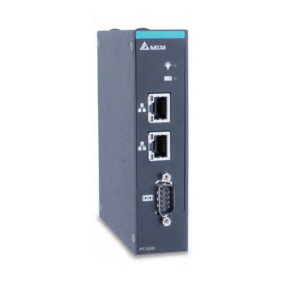
De lta Em b ed d ed S ys t e m O per at i on M a n ua l- E 20 0 S er i es 1.1 Overview IPC-E200 is an embedded system featuring low consumption, high-performance and sealed fan-less design. In addition, the product is certified to IP40 with solid structure and anti-vibration function that can deliver excellent performance over wide temperature range. -
Page 10: Hardware Specification
Ch a pt er 1 Pr o duc t Spec if ic a t i o n 1.3 Hardware specification Item Specification Intel® Celeron N3350 2GB DDR3L 1600MHz, max. up to 8GB 64GB mSata SSD Network Intel® i211AT Gigabit Ethernet Controller x2 Expansion Full-size mini PCIe for wireless module expansion RS-232/ RS-422/ RS-485, default is RS-232 for BIOS setting, please... -
Page 11: Dimensions
De lta Em b ed d ed S ys t e m O per at i on M a n ua l- E 20 0 S er i es 1.4 Dimensions Unit:mm 1 - 4... -
Page 12: Chapter 2 I/O Interface
Chapter 2 I/O Interface Table of Contents Diagram of I/O interface ................2-2 Interface description .................. 2-3 2.2.1 Serial port ....................2-3 2.2.2 USB 2.0 ....................2-3 2.2.3 RJ-45 connector ..................2-4 2.2.4 VGA ......................2-4 2.2.5 DC24V power supply ................. 2-5 2.2.6 DI/DO ..................... -
Page 13: Diagram Of I/O Interface
D e l t a E m b e d d e d S ys t e m O p e r a t i o n Ma n u a l - E 2 0 0 S e r i e s 2.1 Diagram of I/O interface Description Description... -
Page 14: Interface Description
C ha pt er 2 I /O I n ter f ac e 2.2 Interface description 2.2.1 Serial port Communication interface Serial port RS-232 RS-422 RS-485 Data- Data+ 2.2.2 USB 2.0 USB 2.0 Signal USB VCC +5V USB Data- USB Data+ 2 - 3... -
Page 15: Connector
D e l t a E m b e d d e d S ys t e m O p e r a t i o n Ma n u a l - E 2 0 0 S e r i e s 2.2.3 RJ-45 connector RJ-45... -
Page 16: Dc24V Power Supply
C ha pt er 2 I /O I n ter f ac e 2.2.5 DC24V power supply DC24V Signal N.C. 2.2.6 DI/DO Signal DI/DO DIO 0 DIO 1 DIO 2 DIO 3 DIO 4 DIO 5 DIO 6 DIO 7 2 - 5... - Page 17 D e l t a E m b e d d e d S ys t e m O p e r a t i o n Ma n u a l - E 2 0 0 S e r i e s MEMO 2 - 6...
-
Page 18: Chapter 3 Ami Bios Utility
Chapter 3 AMI BIOS Utility Table of Contents Starting BIOS ..................... 3-2 Hotkey shortcuts ..................3-2 Main menu ....................3-2 Advanced menu ..................3-3 Chipset menu ..................... 3-4 Security menu .................... 3-4 Boot menu ....................3-5 Save & Exit menu ..................3-5 COM port setting.................. -
Page 19: Starting Bios
De l ta Em bed d ed S ys t e m O per at i on M a n ua l- E 20 0 S er i es 3.1 Starting BIOS The AMI UEFI BIOS provides users with a built-in setup program to modify system configuration based on the following steps: 1. -
Page 20: Advanced Menu
Ch a pt er 3 A MI BIO S Fu nc t i o n 3.4 Advanced menu The menu contains monitoring of CPU temperature, output voltage of the board; displays hardware parameters which includes CPU, memory, USB and COM. CPU Configuration ... -
Page 21: Chipset Menu
De l ta Em bed d ed S ys t e m O per at i on M a n ua l- E 20 0 S er i es 3.5 Chipset menu The menu provides advanced settings for chipset modifications. 3.6 Security menu The menu contains setting up administrator password to access BIOS Setup interface and password to start the computer. -
Page 22: Boot Menu
Ch a pt er 3 A MI BIO S Fu nc t i o n 3.7 Boot menu The menu provides settings include boot configuration and boot option priorities for SSD as defaults in the 3.8 Save & Exit menu The menu contains resetting BIOS parameters but modification are NOT recommended unless necessary. -
Page 23: Com Port Setting
De l ta Em bed d ed S ys t e m O per at i on M a n ua l- E 20 0 S er i es 3.9 COM port setting Enter Advanced menu and select F81804 Super IO Configuration. For COM port type setting, select Serial Port 1. -
Page 24: Dio Setting
Ch a pt er 3 A MI BIO S Fu nc t i o n Click Select Mode and choose RS232 or RS422 or RS485 for COM type. The default COM setting is RS232. Complete the setup by clicking “F4” to save and exit. 3.10 DIO setting The default setting of DIO is enabled (Enable) with pin 1 to 4 as Out and pin 5 to 8 as In. - Page 25 De l ta Em bed d ed S ys t e m O per at i on M a n ua l- E 20 0 S er i es Continue to select Onboard Device Configuration, Onboard DIO Configuration. 3 - 8...
- Page 26 Ch a pt er 3 A MI BIO S Fu nc t i o n When turning on the computer and DIO Modification is Disabled, this does NOT mean that the function is closed. Select from DIO port 1 to 8 and view each pin status, with default status below. 3 - 9...
- Page 27 De l ta Em bed d ed S ys t e m O per at i on M a n ua l- E 20 0 S er i es To modify DIO configuration, first select Enable for DIO Modification. Select from DIO port 1 to 8 for setting pin status. Complete the setup by clicking “F4”...
-
Page 28: Hardware Replacement
Chapter 4 Hardware Replacement Table of Contents Replace Memory (RAM) ..............4-2 Replace mSATA SSD ................. 4-4 4 - 1... -
Page 29: Replace Memory (Ram)
De lta Em b ed d ed S ys t e m O per at i on M a n ua l- E 20 0 S er i es 4.1 Replace Memory (RAM) ✽ Any component replacement and repair of the host machine by users will lose the original product guarantees. - Page 30 Ch a pt er 4 Har d war e Re p lac em en t “In the meantime”, the metal part of the clip is to be pulled outward and the RAM flicks Step 4 up in a slope angle to be pulled out. Step 5 Insert and press the RAM firmly into the slot until it is seated.
-
Page 31: Replace Msata Ssd
De lta Em b ed d ed S ys t e m O per at i on M a n ua l- E 20 0 S er i es Step 6 When RAM installation is complete, please attach the side covers back to the chassis and fasten all screws. - Page 32 Ch a pt er 4 Har d war e Re p lac em en t Step 3 Remove the fixed screws for mSATA SSD and pull out the SSD once it flicks up in a slope angle. 4 - 5...
- Page 33 De lta Em b ed d ed S ys t e m O per at i on M a n ua l- E 20 0 S er i es mSATA SSD is installed in CN5, the board is marked mSata / USB / PCIe. Step 4 Step 5 Tilt the SSD and insert it into the slot.
-
Page 34: Chapter 5 Transportation & Storage Requirements
Chapter 5 Transportation & Storage Requirement Table of Contents Unpack and check the delivery package ............. 5-2 Transportation .................... 5-2 Storage requirements ................. 5-2 5 - 1... -
Page 35: Unpack And Check The Delivery Package
De l ta Em bed d ed S ys t e m O per at i on M a n ua l- E 20 0 S er i es 5.1 Unpack and check the delivery package Please take note of the following when opening the delivery: ●...
Need help?
Do you have a question about the IPC-E200 Series and is the answer not in the manual?
Questions and answers