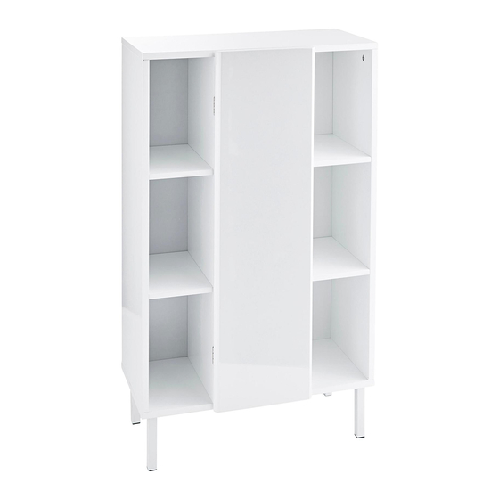
Summary of Contents for Dahlia YO888
- Page 1 Storage Unit Assembly Instructions - please keep for future reference YO888 464/3944 Dimensions Width - 57cm Depth - 28.5cm Height - 96.5cm Important – Please read these instructions fully before starting assembly Issue 1 - 12/12/17...
- Page 2 Safety and Care Advice Important – Please read these instructions fully before starting assembly • Check you have all the • During assembly do not stand • We do not components and tools listed on or put weight on the product, recommend the use page 2 this could cause damage.
- Page 3 Components - Panels Please check you have all the panels listed below Right Side Panel x 1 Middle Left Panel x 1 Left Side Panel x 1 (80(w) x 26.5(d) cm) (80(w) x 26.5(d) cm) (80(w) x 26.5(d)cm) Middle Right Panel x 1 Top Panel x 1 Base Panel x 1 (80(w) x 26.5(d) cm)
- Page 4 Components - Fittings Note: may be supplied than are required. Male Camlocks x 24 Female Camlocks x 24 Shelf Supports x 8 30mm Dowel x 8 35mm Screw x 8 12mm Screw x 9 Push Catch x 1 18mm Screw x 1 Hinges x 2 14mm Screw x 24 14mm Screw x 16...
- Page 6 Assembly Instructions Step 1 1. Into Left Side Panel 1 insert a total of 4 x Male Camlocks B as shown. 2. Locate 2 x Open Shelves onto Male Camlocks 3. Into holes shown in Side Panels 7 Insert 4 x Female Camlocks as shown.
- Page 7 Assembly Instructions Step 3 1. Into Right Side Panel 3 insert a total of 4 x Male Camlocks B as shown. 2. Locate 2 x Open Shelves onto Male Camlocks 3. Into holes shown in Side Panels 7 Insert 4 x Female Camlocks as shown.
- Page 8 Assembly Instructions Step 5 1. Into the ends of Panels 3 and 4 insert a total of 8 x Dowels C as shown. 2. Locate Base Panel 6 onto Dowels 3. Connect Panel 6 using 8 x Screws E as shown Step 6 1.
- Page 9 Assembly Instructions Step 7 1. To Top Panel 5 install Push Catch G using 4 x Screw K Step 8 1. Into the underside of Top Panel 5 install 8 x Male Camlocks A as shown 2. Slide Back Panels 11 and 2 x 10 into Position 3.
- Page 10 Assembly Instructions Step 9 1. On the reverse of the unit install a total of 12 x Panel Stiffeners as shown using 12 x Screws k Step 10 1. Connect Catch Plate L to Door 8 using 1 x Screw F 2.
- Page 11 Assembly Instructions Step 11 1. To Top Panel 1 x Wall strap L as shown using 1 x Screw The unit is floor standing, but it is recommended that the unit is secured to the wall. 1. Move the unit into desired position.

Need help?
Do you have a question about the YO888 and is the answer not in the manual?
Questions and answers