
Summary of Contents for Transducer Techniques SST
- Page 1 SMART SENSOR TRANSMITTER PLUG AND PLAY IEEE 1451.4 COMPLIANT OPERATOR MANUAL Transducer Techniques...
-
Page 2: Table Of Contents
TABLE OF CONTENTS TEDS IEEE 1451.4 INTRODUCTION .................. 3 SST TRANSMITTER INTRODUCTION ................4 RECEIVING & UNPACKING YOUR TRANSMITTER ............5 SAFETY CONSIDERATIONS ....................5 TRANSMITTER FIELD WIRING ..................6 READOUTS IN TEDS MODE ....................7 PROGRAMMING YOUR TRANSMITTER ................8 - COMMUNICATIONS ...................... -
Page 3: Teds Ieee 1451.4 Introduction
1. TEDS IEEE 1451.4 INTRODUCTION Model SST is a TEDS IEEE 1451.4 Plug and Play Smart Transmitter for TEDS IEEE 1451.4 com- pliant Load Cell / Torque Sensors. Such sensors incorporate an EEPROM which specifies the type of sensor, its interface, and technical information such as sensitivity, bridge type, excitation, etc. -
Page 4: Sst Transmitter Introduction
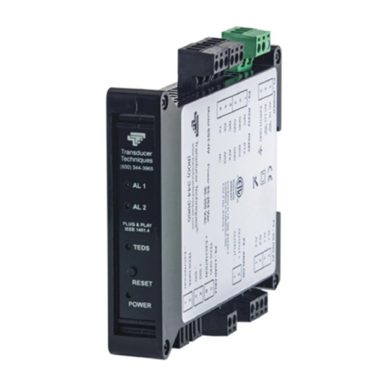
2. SST TRANSMITTER INTRODUCTION The SST Transmitter is an extremely accurate and versatile DIN rail transmitter for Load Cell / Torque Sensors. Standard features include: Accuracy of 0.01% of full scale ± 1 count. Update rate to 60/sec in 60 Hz noise environments or 50/sec in 50 Hz noise environments. -
Page 5: Receiving & Unpacking Your Transmitter
Your transmitter was carefully tested and inspected prior to shipment. Should the transmitter be damaged in shipment, notify the freight carrier immediately. In the event the transmitter is not configured as ordered or is inoperable, please contact Transducer Techniques. 4. SAFETY CONSIDERATIONS Warning: Use of this transmitter in a manner other than specified may impair the protection of the device and subject the user to a hazard. -
Page 6: Transmitter Field Wiring
5. TRANSMITTER FIELD WIRING - 6 -... -
Page 7: Readouts In Teds Mode
The excitation supply is automatically set to the correct value, and the SST then calculates the correct scaling to calibrate the SST and transducer as a system. The jumper on the signal conditioner board must be set for the 50 mV range. See Section 10. -
Page 8: Programming Your Transmitter
RS232 cable with rear view of DB9 connector to PC If your PC only has a USB port but no RS232 port, connect the 3-wire RS232 cable SST- RS232-AD9 to the RS232 to USB adapter cable SST-USB-AD9. This adapter cable is recom- mended because it contains an FTDI chip, which is compatible with all versions of Windows, including Windows 7 and 10. -
Page 9: Communications
The Communications Setup screen will automatically appear a few seconds after the splash screen. Use this screen to select your communications Protocol, Device Type, and Commu- nications Type. Selecting “None” for Communications Type allows you develop a setup file without being connected to an actual transmitter. - 9 -... - Page 10 In the Establish Communications screen, select your Com Port and 9600 and the Baud Rate. You will be able to change your protocol and baud rate later under the Communication setup tab. Click on Establish, and the two fields at the bottom of the screen should turn green. Click on the Main Menu button to open the Main Menu screen.
-
Page 11: Signal & Control Inputs
To get to the Input+Display tab, click on DPM => Get Setup to retrieve the current setup information from your DPM transmitter, then on View => Setup. Use the Input+Display screen to set up Signal Input, Display, and Control Inputs. The software reads the signal conditioner type, but not the range, which is set by jumpers. -
Page 12: Scaling
Click on the Scaling tab to scale your transmitter. If a TEDS transmitter is detected, you can enable or disable three items: Auto-Tare, TEDS LED indicator, and TEDS Plug and Play operation. Front Panel Tare does not apply to transmitters. The section “TEDS Data (Read Only)”... -
Page 13: Filtering
Click on the Filter tab to set to set up filtering for your readings. The adaptive threshold modifies the time constant in response to noise. Under Time Constant, the filter time constant can be automatic, be set to batch, be specified in seconds, or be turned off. -
Page 14: Relay Alarms
Click on the Relay Alarms tab to set up your transmitter’s two solid state relays, which are standard. For a complete explanation of Dual Relay Operation, see page 21. For detailed help on any data entry field, select that field and press the F1 key. Click on the Communication tab to view the communication parameters that you used to establish default communications with your transmitter. -
Page 15: Analog Output
Click on the Analog Out tab to scale your analog output. Under Range, select 4-20 mA, 0-20 mA, 0-10V or -10V to +10V. To create the two endpoints of your analog output range, type in your Lo Range Reading and Hi Range Reading. For detailed help on any data entry field, select that field and press the F1 key. - Page 16 - List presents the latest internal readings in a 20-row by 10-column table. Press Pause at any time to freeze the display. Press Print for a hardcopy. - Plot generates a plot of internal readings vs. time in seconds. It effectively turns the transmitter-PC combination into a printing digital oscilloscope.
- Page 17 The Jumpers pull-down menu shows jumper positions for the load cell signal conditioner board and the main board, duplicating information in this manual. Jumpers - 17 -...
-
Page 18: Opening Your Transmitter Case
8. OPENING YOUR TRANSMITTER CASE WHEN TO CHANGE JUMPERS Depending on your desired setup, the internal jumpers of the transmitter may need to be moved from their default positions to meet your needs. This will require opening the case. Note that while Instrument Setup Software senses the circuit board type, it does not sense jumper settings, and the corresponding information has to be entered manually. -
Page 19: Main Board Jumper Settings
9. MAIN BOARD JUMPER SETTINGS Serial Signal Duplex Jumpers Termination Resistor* E6 a = Transmit Full None E6 c = Receive RS485 Half E6 b + d** E6 c RS232 Full None None The termination resistor jumper settings should only be selected if the transmitter is the last device on an RS485 line longer than 200 feet (60 m). -
Page 20: Load Cell Signal Conditioner Board Jumper Settings
10. LOAD CELL SIGNAL CONDITIONER BOARD JUMPER SETTINGS Load Cell & Microvolt Ranges FS Input Jumpers ±20.000 mV ±50.000 mV ±100.00 mV ±250.00 mV ±500.00 mV 11. TRANSMITTER CALIBRATION All analog input and analog output ranges of the transmitter have been digitally calibrated at the factory prior to shipment using calibration equipment certified to NIST standards. -
Page 21: Dual Relay Operation
12. DUAL RELAY OPERATION Dual AC/DC solid state relays rated 120 mA are standard for alarm or setpoint control and are independently set up via the “Relay Alarms” tab of Instrument Setup Software. For online help with any data entry field, press the F1 key. Setpoint. - Page 22 Deviation. A positive number that can be added or subtracted from the setpoint, depending on the Deviation Type, to determine when an alarm becomes Active or Inactive. Alarm State. If “Active High” is selected, the Active Alarm State is defined as being above the setpoint.
- Page 23 temporarily grounding one of the transmitter’s control inputs, which has been set to Function Reset under the “Input+Display” tab. Alarms 1,2 No. Rdgs to Alarm. Selections are binary steps from 1 to 128. This is the number of consecutive alarm readings that must occur to create an Active alarm. Numbers higher than 2 provide some Alarm filtering so that 1 or 2 noisy readings do not cause an Active Alarm.
-
Page 24: Modbus Protocol Transmitter Communications
13. MODBUS PROTOCOL TRANSMITTER COMMUNICATIONS 1.0 GENERAL The Modbus capability conforms to the Modbus over Serial Line Specification & Implemen- tation Guide, V1.0. Both the Modbus RTU and Modbus ASCII protocols are implemented. This 5-page manual section provides some of the key programmable Modbus features. Modbus RTU Baud Rate ... - Page 25 4.0 COMMUNICATIONS SETUP Parameters selectable via Instrument Setup software, which is downloadable from our website: Serial Protocol ....... Custom ASCII, Modbus RTU, Modbus ASCII Modbus ASCII Gap Timeout ... 1 sec, 3 sec, 5 sec, 10 sec Baud Rate ........300, 600, 1200, 2400, 4800, 9600, 19200 Parity ..........
- Page 26 FC08: Diagnostics Checks communications between the Master and Slave, and returns the count in the Modbus Slave counters (which are reset when the meter is reset). Hex Sub Data Response Function Description Send Data Code 00 00 Same Returns Query Data (N x 2 bytes). Echo Request. as sent 00 01 Restarts Communications.
- Page 27 6.0 SUPPORTED EXCEPTION RESPONSE CODES Code Name Error Description ---- -------------------- ------------------------------------------------------ Illegal Function Illegal Function Code for this Slave. Only hex Function Codes 03, 04, 05, 08, 10 (dec 16) are allowed. Illegal Data Address Illegal Register Address for this Slave. Illegal Data Value Illegal data value or data length for the Modbus protocol.
- Page 28 Modbus ASCII Format Byte Number Action Request Response Request Response Request Response Request Response Request LRC CR Response Exception EC LRC CR Response DD* = (DD DD) times NR (Number of Registers) 8.0 MESSAGE EXAMPLES All examples are for Transmitter Address = 01 and No Parity. Modbus RTU Modbus ASCII Ser_4 ->...
-
Page 29: Custom Ascii Protocol Transmitter Communications
14. CUSTOM ASCII PROTOCOL TRANSMITTER COMMUNICATIONS 1.0 SERIAL COMMUNICATION FORMAT The Custom ASCII serial communication format for both RS232 and RS485 is the following: Mode ....Full Duplex (Separate transmit and receive lines) and Half Duplex (RS485 only) Baud Rate ..300, 600, 1200, 2400, 4800, 9600, 19200 selectable with Instrument Setup software. - Page 30 Addressing of transmitters can be set with Instrument Setup software. 4.0 COMMAND MODE OVERVIEW Using the Custom ASCII protocol, SST transmitters operate in the Command Mode only. In this mode, the device does not send data automatically, but responds to commands received from a host computer.
- Page 31 Char # Character Description Command Identifier. Recognition Character. Device Address. 0 addresses all devices, 1-V specific devices. Command Function Sub-command. Number of Bytes of RAM or Words (2 Bytes) of non-volatile memory data being transferred. CHAR 2 - Address Codes A Serial Communications Address Code from 1 to V follows the “*”...
- Page 32 Peak value reset *1C3 Remote display reset *1C4 Valley reset *1C9 Tare function *1CA Tare reset *1CB 6.0 READING AND WRITING TO RAM AND NONVOLATILE MEMORY CHAR 1, 2 The Recognition character and Meter Address Code are the same as shown in previous table. CHAR 3 Command character: Read bytes from RAM Memory...
- Page 33 General, Reading and Writing Ram Memory Data RAM memory data is read and written as a continuous string of bytes consisting of 2 hex characters (0-9,A-F) per byte. Included in the command are the total number of bytes to be transferred and the most significant address in RAM of the continuous string of bytes.
-
Page 34: Sst Transmitter Specifications
15. SST TRANSMITTER SPECIFICATIONS Load Cell & Microvolt Input Signal Conditioner Full scale ranges ......20.000 mV, 50.000 mV, 100.00 mV, 250.00 mV, 500.00 mV Input resistance ........................ 1 Gohm Input accuracy at 25°C ..............± 0.01% of full span ±2 counts Max applied voltage ........................ - Page 35 Modbus Compliance ........Modbus over Serial Line Specification V1.0 (2002) Serial connector ................. Detachable screw terminal plugs Baud rates ............300, 600, 1200, 2400, 4800, 9600, 19200 baud Output isolation ........Safety rated to 250 Vrms, 4.2 kV per High Voltage Test Dual Relay Output (standard) Relay type ...........
-
Page 36: Accessories
16. ACCESSORIES - 36 -... - Page 37 Transmitter Power Cable. Also usable with TTI DPM-3 digital panel meters. SST-RS232-AD9 Serial Output Cable to PC COM Port SST-USB-AD9 Serial to USB Adapter Cable & Disk. Can be connected to SST-RS232- AD9. DPM-3-DLS Data Logging Software DPM-3-TRES TEDS Reader_Editor Software...
-
Page 38: Warranty
Any of our products which, under normal operating conditions, proves defective in material or in workmanship within one (1) year from the date of shipment by Transducer Techniques, will be repaired or replaced free of charge provided that you obtain a return material... - Page 39 Load Cells Force/Torque Sensors (800) 344-3965 E-mail: tti@ttloadcells.com www.transducertechniques.com Transducer Techniques Temecula, CA 92590 - 39 -...
Need help?
Do you have a question about the SST and is the answer not in the manual?
Questions and answers