
Related Manuals for Radicon J Series

Summary of Contents for Radicon J Series
- Page 1 Series J Shaft Mounted Gearbox Technical Up to - 600kW /57,000 Nm Industrial Gearbox CJ-1.00GBD0111...
- Page 2 SERIES J PRODUCTS IN THE RANGE Serving an entire spectrum of mechanical drive applications from food, energy, mining and metal; to automotive, aerospace and marine propulsion, we are here to make a positive difference to the supply of drive solutions. Series A Series BD Series BS...
- Page 3 Fax: +91 2692 36559 Tel: +43 7 229 618 91 Fax: +43 7 229 618 84 Radicon Transmission DENMARK (Thailand) Ltd Radicon Transmission USA Germany 700/43 Moo 6 240 East 12th Street Benzler Transmission A/S Tel: 0800 350 40 00...
- Page 4 ATEX Compliance Assured Total compliance with the ATEX Directive safeguarding the use of industrial equipment in potentially explosive atmospheres is assured for users of our geared products. Certification is available for standard gearboxes and geared motors with badging displaying the CE Mark and the Ex mark, name and location of the manufacturer, designation of series or type, serial number, year of manufacture, Ex symbol and equipment group/category.
- Page 5 SERIES J...
-
Page 6: Table Of Contents
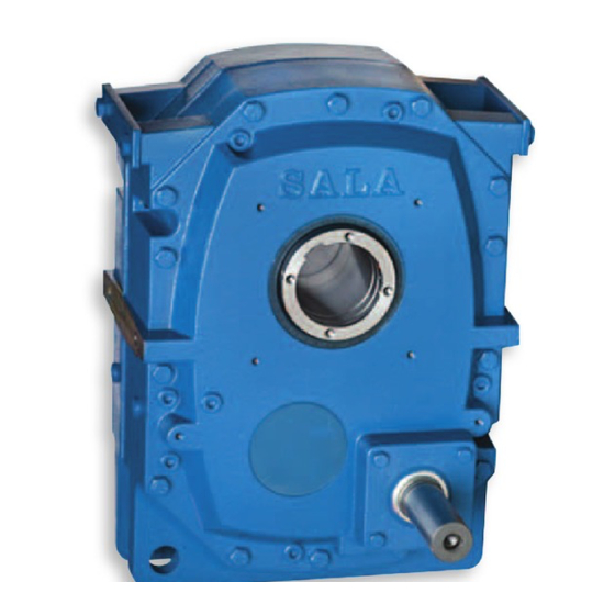
SERIES J CONTENTS 0203 Series J Shaftmounted Speed Reducers, General Description Unit Designations Selection Procedure 6 - 7 Power ratings / Thermal power ratings 1-stage 2-stage 15:1 9 - 10 2-stage 20:1 2-stage 25:1 12 - 13 Dimensions J 11 - 71 1-stage 14 - 15 J 100 - 125 1-stage 16 - 17... - Page 7 SERIES J GENERAL DESCRIPTION 0201 Series J Shaft Mounted Speed Reducers are high quality products, submitted to intense quality control and manufactured with the highest precision. — Worldwide after sales service — 19 types up to 600 kW, 57000 Nm —...
-
Page 8: Unit Designations
SERIES J UNIT DESIGNATIONS 0201 9 10 11 12 13 14 15 16 17 18 19 20 EXAMPLE 1 - SERIES J 20 - ADDITIONAL FEATURES SHAFT MOUNTED GEARS RANGE - NONE REQUIRED - PULLEY OR/AND MOTOR - PRE-REDUCER TYPE M 2, 3, 4 - SIZE OF UNIT 1 1 A 1 2 A... -
Page 9: Selection Procedure
SERIES J SELECTION PROCEDURE 0203 Start Definition of service factor The torque ratings apply to service factor fb = 1,0. Mechanical Rating The service factor fb = 1,0 gives continual operation 4 to Determine the demand of power (P kW) or torque (T Nm) and 8 hours a day at a uniform load without shocks and with speed (n... - Page 10 SERIES J SELECTION PROCEDURE 0203 Service factors Table 1. Service factor fb Daily operation 4 hours 8 hours 16 hours 24 hours Starts per hour <10 10-200 >200 <10 10-200 >200 <10 10-200 >200 <10 10-200 >200 Load classification Table 2. Description of load classifications Description Load Example...
- Page 11 SERIES J POWER RATINGS - Single Reduction 0203 J100 J110 J125 J140 J160 J190 0 - 60 60 - 80 0,85 0,95 80 - 100 0,85 0,95 100 - 200 0,85 0,95 Specification of factor for V-belt forces in different angles. Power ratings have to be multiplied with this factor for sizes J100 - 190 when motor is located in angle 90 - 210 °.
- Page 12 SERIES J POWER RATINGS - Double Reduction 15:1 0203 Double reduction The torque is shown in Nm (1 Nm = 0.102 kpm = 0.7376 lbf.ft) 15.09:1 15.22:1 15.45:1 15.39:1 14.61:1 Output for driven for driven for driven for driven for driven pulley pulley pulley...
-
Page 13: 2-Stage 15:1
SERIES J POWER RATINGS - Double Reduction 15:1 0203 Double reduction The torque is shown in Nm (1 Nm = 0.102 kpm = 0.7376 lbf.ft) J100 J110 J125 J140 J160 J190 15.94:1 15.95:1 14.79:1 14.75:1 15.04:1 15.71:1 Output for driven for driven for driven for driven... - Page 14 SERIES J POWER RATINGS - Double Reduction 20:1 0203 Double reduction The torque is shown in Nm (1 Nm = 0.102 kpm = 0.7376 lbf.ft) J100 J110 J125 J140 J160 J190 19.99:1 19.95:1 19.91:1 19.97:1 20.62:1 20.92:1 Output for driven for driven for driven for driven...
- Page 15 SERIES J POWER RATINGS Double Reduction 25:1 0203 Double reduction The torque is shown in Nm (1 Nm = 0.102 kpm = 0.7376 lbf.ft) 24.96:1 24.38:1 24.17:1 24.72:1 24.44:1 Output for driven for driven for driven for driven for driven pulley pulley pulley...
- Page 16 SERIES J POWER RATINGS Double Reduction 25:1 0203 Double reduction The torque is shown in Nm (1 Nm = 0.102 kpm = 0.7376 lbf.ft) J100 J110 J125 J140 J160 J190 25.00:1 24.95:1 24.86:1 25.61:1 24.36:1 25.53:1 Output for driven for driven for driven for driven for driven...
- Page 17 SERIES J DIMENSIONS - SINGLE REDUCTION 0202 J11 - 71 Single Reduction HFx45° ° 90° +0 ° øS øM ±0.5° Please note: Dimensions R, T, T1, T2, T3 are not machined, deviations can occur. Size Ratio max min J11A 4.94:1 137 16 350 240 90 105 140 200 108 83 J11B...
- Page 18 SERIES J DIMENSIONS - SINGLE REDUCTION KIBO 0201 J11 - 71 Single Reduction Please note: Dimensions R, T, T1, T2, T3 are not machined, deviations can occur. Size Ratio max min J11A 4.94:1 116 11.6 36.4 65 350 240 87 102 140 200 108 83 J11B 4.94:1 116 11.6 36.4 65 350 240...
- Page 19 SERIES J DIMENSIONS - SINGLE REDUCTION 0202 J100 - 125 Single Reduction Dimensions for threaded holes at gearhouse sides, see page 53. Please note: Dimensions R, T, T1, T2, T3 are not machined, deviations can occur. Size Ratio max min J100 286 10 142 180 755 500...
- Page 20 SERIES J DIMENSIONS - SINGLE REDUCTION KIBO 0202 J100 - 125 Single Reduction Dimensions for threaded holes at gearhouse sides, see page 53. Please note: Dimensions R, T, T1, T2, T3 are not machined, deviations can occur. Size Ratio J100 J110 J125 133.5 168.5 242.5 277.5 280...
- Page 21 SERIES J DIMENSIONS - DOUBLE REDUCTION 0201 J12 - 72 Double Reduction HFx45° ° 90° +0 ° øS øM ±0.5° Please note: Dimensions R, T, T1, T2, T3 are not machined, deviations can occur. Size Ratio max min J12A 15/25:1 137 14 83 350 240 12 65 94 109 140 200 108 100 272 15 J12B 15/25:1 137 14...
- Page 22 SERIES J DIMENSIONS - DOUBLE REDUCTION KIBO 0206 J12 - 72 Double Reduction Please note: Dimensions R, T, T1, T2, T3 are not machined, deviations can occur. Size Ratio max min J12A 15/25:1 116 11.6 47 83 350 240 12 87 102 140 200 108 100 272 15 29 J12B 15/25:1 116 11.6 47 83 350 240 12...
- Page 23 SERIES J DIMENSIONS - DOUBLE REDUCTION 0202 J100 - 190 Double Reduction Dimensions for threaded holes at gearhouse sides, see page 53. Please note: Dimensions R, T, T1, T2, T3 are not machined, deviations can occur. Size Ratio max min J100 15/20/25:1 286 10 31.5 99 180 755 500 30...
- Page 24 SERIES J DIMENSIONS - DOUBLE REDUCTION KIBO 0202 J100 - 190 Double Reduction Dimensions for threaded holes at gearhouse sides, see page 53. Please note: Dimensions R, T, T1, T2, T3 are not machined, deviations can occur. Size Ratio max min J100 15/20/25:1 274 22 14.5 99 180 755 500 30...
- Page 25 SERIES J POWER RATINGS V-BELT TRANSMISSIONS 0201 V-belt V-belt Pulley Motor- Pulley Gear Pulley Pulley Motor pulley length mount unit Ratio type type 0.37 1,41 1,13 90S-8 1250 4,48 1SPZ 1,37 1,11 *80C-8 1250 4,48 1SPZ 1,67 1,14 90S-8 1180 3,80 1SPZ 1,49...
- Page 26 SERIES J POWER RATINGS V-BELT TRANSMISSIONS 0201 V-belt V-belt Pulley Pulley Motor- Gear Pulley Pulley Motor pulley length mount unit Ratio type type 1,50 2260 1,28 1,18 112M-8 1800 4,44 2SPZ 2244 1,29 1,19 *100LC-8 1800 4,44 2SPZ 2009 1,44 1,16 112M-8 1600...
- Page 27 SERIES J POWER RATINGS V-BELT TRANSMISSIONS 0201 V-belt V-belt Pulley Motor- Pulley Gear Pulley Pulley Motor pulley length mount unit Ratio type type 2,20 2673 1,09 1,08 132S-8 1700 3,71 2SPZ 2320 1,25 1,13 112M-6 1700 4,20 2SPZ 2468 1,18 1,12 112M-6 1700...
- Page 28 SERIES J POWER RATINGS V-BELT TRANSMISSIONS 0201 V-belt V-belt Pulley Pulley Motor- Gear Pulley Pulley Motor pulley length mount unit Ratio type type 2,20 1380 1,09 1,12 112M-6 1320 2,53 2SPZ 1360 1,10 1,09 112M-6 1500 4,00 2SPZ 1368 1,61 1,13 *100LC-6 1400...
- Page 29 SERIES J POWER RATINGS V-BELT TRANSMISSIONS 0201 V-belt V-belt Pulley Pulley Motor- Gear Pulley Pulley Motor pulley length mount unit Ratio type type 2,20 1,54 1,19 90L-2 1250 2,84 1SPZ 1,56 1,24 100LA-4 1180 1,40 1SPZ 1,62 1,14 90L-2 1400 4,48 1SPZ 1,61...
- Page 30 SERIES J POWER RATINGS V-BELT TRANSMISSIONS 0201 V-belt V-belt Pulley Motor- Pulley Gear Pulley Pulley Motor pulley length mount unit Ratio type type 3,00 1993 1,45 1,21 *112MB-6 1700 2,63 2SPZ 1986 1,46 1,19 *112MB-6 2000 4,21 2SPZ 2066 1,07 1,19 *112MB-6 1600...
- Page 31 SERIES J POWER RATINGS V-BELT TRANSMISSIONS 0201 V-belt V-belt Pulley Motor- Pulley Gear Pulley Pulley Motor pulley length mount unit Ratio type type 3,00 1442 1,50 1,23 132S-6 1500 2,00 2SPZ 1456 1,51 1,22 132S-6 1700 3,16 2SPZ 1455 1,03 1,21 132S-6 1400...
- Page 32 SERIES J POWER RATINGS V-BELT TRANSMISSIONS 0201 V-belt V-belt Pulley Pulley Motor- Gear Pulley Pulley Motor pulley length mount unit Ratio type type 4,00 5669 J100 1,76 1,29 160MA-8 2500 4,25 3SPZ 4927 1,02 1,27 160MA-8 2240 3,77 3SPZ 3890 1,29 1,31 132MA-6...
- Page 33 SERIES J POWER RATINGS V-BELT TRANSMISSIONS 0201 V-belt V-belt Pulley Motor- Pulley Gear Pulley Pulley Motor pulley length mount unit Ratio type type 4,00 1631 1,26 1,35 132MA-6 1600 1,70 2SPZ 1648 1,34 1,32 132MA-6 1800 2,68 2SPZ 1670 1,74 1,03 112M-4 1900...
- Page 34 SERIES J POWER RATINGS V-BELT TRANSMISSIONS 0201 V-belt V-belt Pulley Motor- Pulley Gear Pulley Pulley Motor pulley length mount unit Ratio type type 4,00 1,74 1,00 112M-4 1320 1,14 1SPZ 1,58 1,35 112M-2 1250 1,32 1SPZ 1,60 1,35 *100LB-2 1180 1,32 1SPZ 1,51...
- Page 35 SERIES J POWER RATINGS V-BELT TRANSMISSIONS 0201 V-belt V-belt Pulley Motor- Pulley Gear Pulley Pulley Motor pulley length mount unit Ratio type type 5,50 1159 1,59 1,04 132MB-6 1500 1,36 2SPZ 1178 1,44 1,33 *112MB-2 1500 2,65 2SPZ 1172 1,28 1,27 *112MB-2 1600...
- Page 36 SERIES J POWER RATINGS V-BELT TRANSMISSIONS 0201 V-belt V-belt Pulley Motor- Pulley Gear Pulley Pulley Motor pulley length mount unit Ratio type type 5,50 1,54 1,07 *112MB-2 1320 1,43 1SPZ 1,67 1,35 *112MB-4 1800 3,41 2SPZ 1,27 1,29 *112MB-2 1250 2,25 2SPZ 1,58...
-
Page 37: Power Ratings V-Belt Transmissions
SERIES J POWER RATINGS V-BELT TRANSMISSIONS 0201 V-belt V-belt Pulley Motor- Pulley Gear Pulley Pulley Motor pulley length mount unit Ratio type type 7,50 2008 1,44 1,40 160M-6 1900 1,77 3SPZ 1921 1,51 1,31 132M-4 1700 1,57 2SPZ 1921 1,51 1,33 132M-4 1800... - Page 38 SERIES J POWER RATINGS V-BELT TRANSMISSIONS 0201 V-belt V-belt Pulley Pulley Motor- Gear Pulley Pulley Motor pulley length mount unit Ratio type type 7,50 1,38 1,23 132M-4 1800 2,67 2SPZ 1,38 1,26 132M-4 1900 2,67 2SPZ 1,38 1,12 132SB-2 1400 1,07 1SPZ 1,44...
- Page 39 SERIES J POWER RATINGS V-BELT TRANSMISSIONS 0201 V-belt V-belt Pulley Motor- Pulley Gear Pulley Pulley Motor pulley length mount unit Ratio type type 9,00 2131 1,36 1,26 160L-6 1900 1,56 3SPZ 2159 1,34 1,09 132MA-4 2000 2,37 2SPZ 2071 1,39 1,09 132MA-4 1600...
- Page 40 SERIES J POWER RATINGS V-BELT TRANSMISSIONS 0201 V-belt V-belt Pulley Motor- Pulley Gear Pulley Pulley Motor pulley length mount unit Ratio type type 9,00 1,30 1,39 132SD-2 1500 2,12 2SPZ 1,56 1,24 132MA-4 1500 1,06 2SPZ 1,56 1,25 132MA-4 1600 1,06 2SPZ 1,31...
- Page 41 SERIES J POWER RATINGS V-BELT TRANSMISSIONS 0201 V-belt V-belt Pulley Motor- Pulley Gear Pulley Pulley Motor pulley length mount unit Ratio type type 11,0 4191 1,19 1,36 *132MB-4 2120 2,37 3SPZ 3927 1,27 1,36 160M-4 2000 2,23 3SPZ 3837 1,30 1,14 *132SC-2 2240...
- Page 42 SERIES J POWER RATINGS V-BELT TRANSMISSIONS 0201 V-belt V-belt Pulley Pulley Motor- Gear Pulley Pulley Motor pulley length mount unit Ratio type type 11,0 2473 1,17 1,36 160M-4 2000 2,23 3SPZ 2531 1,14 1,37 *132MB-4 1800 1,41 3SPZ 2490 1,16 1,35 *132MB-4 2000...
- Page 43 SERIES J POWER RATINGS V-BELT TRANSMISSIONS 0201 V-belt V-belt Pulley Motor- Pulley Gear Pulley Pulley Motor pulley length mount unit Ratio type type 11,0 1674 1,00 1,33 160L-6 1700 1,00 2SPA 1665 1,74 1,36 *132MB-4 1800 1,49 3SPZ 1672 1,00 1,33 *132MB-4 1600...
- Page 44 SERIES J POWER RATINGS V-BELT TRANSMISSIONS 0201 V-belt V-belt Pulley Pulley Motor- Gear Pulley Pulley Motor pulley length mount unit Ratio type type 11,0 1145 1,31 1,16 *132SC-2 1600 2,00 2SPZ 1128 1,11 1,14 *132SC-2 1500 2,00 2SPZ 1120 1,33 1,07 *132MB-4 1500...
- Page 45 SERIES J POWER RATINGS V-BELT TRANSMISSIONS 0201 V-belt V-belt Pulley Motor- Pulley Gear Pulley Pulley Motor pulley length mount unit Ratio type type 15,0 5600 J100 1,79 1,21 180L-6 2650 1,90 2SPA 4827 1,04 1,30 160M-2 2240 4,03 3SPZ 4827 1,04 1,33 160M-2...
- Page 46 SERIES J POWER RATINGS V-BELT TRANSMISSIONS 0201 V-belt V-belt Pulley Motor- Pulley Gear Pulley Pulley Motor pulley length mount unit Ratio type type 18,5 14338 J125 1,41 1,27 *180LB-6 3150 3,15 3SPA 13656 J125 1,48 1,28 *180LB-6 3150 3,00 3SPA 13378 J125 1,52...
- Page 47 SERIES J POWER RATINGS V-BELT TRANSMISSIONS 0201 V-belt V-belt Pulley Motor- Pulley Gear Pulley Pulley Motor pulley length mount unit Ratio type type 18,5 4912 1,02 1,28 200MLA-6 2360 1,88 3SPA 4919 1,02 1,31 180M-4 2360 1,67 2SPA 4706 1,06 1,27 *160LB-4 2120...
- Page 48 SERIES J POWER RATINGS V-BELT TRANSMISSIONS 0201 V-belt V-belt Pulley Pulley Motor- Gear Pulley Pulley Motor pulley length mount unit Ratio type type 18,5 1574 1,34 1,25 160L-2 1900 1,05 2SPZ 1568 1,55 1,26 180M-4 2650 2,64 2SPA 1555 J100 1,51 1,27 *180LB-6...
- Page 49 SERIES J POWER RATINGS V-BELT TRANSMISSIONS 0201 V-belt V-belt Pulley Pulley Motor- Gear Pulley Pulley Motor pulley length mount unit Ratio type type 22,0 3067 1,41 1,35 180M-2 2120 1,75 3SPZ 2956 1,42 1,29 *160LB-2 2240 2,81 3SPZ 2964 1,41 1,33 180L-4 2360...
- Page 50 SERIES J POWER RATINGS V-BELT TRANSMISSIONS 0201 V-belt V-belt Pulley Pulley Motor- Gear Pulley Pulley Motor pulley length mount unit Ratio type type 30,0 10363 J110 1,37 1,14 225SMB-6 3150 1,79 2SPB 9895 J110 1,43 1,13 *200MLC-6 3000 1,70 2SPB 9374 J110 1,51...
- Page 51 SERIES J POWER RATINGS V-BELT TRANSMISSIONS 0201 V-belt V-belt Pulley Motor- Pulley Gear Pulley Pulley Motor pulley length mount unit Ratio type type 37,0 19112 J125 1,06 1,38 250SMA-6 3350 2,14 3SPB 19188 J140 1,60 1,37 250SMA-6 3750 2,68 3SPB 1038 19112 J125...
- Page 52 SERIES J POWER RATINGS V-BELT TRANSMISSIONS 0201 V-belt V-belt Pulley Pulley Motor- Gear Pulley Pulley Motor pulley length mount unit Ratio type type 45,0 23336 J140 1,32 1,13 *250SMB-6 3750 2,68 3SPB 1038 21980 J140 1,40 1,15 280SA-6 3750 2,54 3SPB 1075 19603...
- Page 53 SERIES J POWER RATINGS V-BELT TRANSMISSIONS 0201 V-belt V-belt Pulley Motor- Pulley Gear Pulley Pulley Motor pulley length mount unit Ratio type type 55,0 13333 J125 1,52 1,13 *225SMC-4 3550 1,89 2SPB 13364 J110 1,06 1,13 *225SMC-4 3550 1,89 2SPB 12622 J125 1,61...
- Page 54 SERIES J POWER RATINGS V-BELT TRANSMISSIONS 0201 V-belt V-belt Pulley Motor- Pulley Gear Pulley Pulley Motor pulley length mount unit Ratio type type 75,0 13017 J110 1,09 1,27 280SA-4 3550 1,69 3SPB 1016 12864 J125 1,58 1,28 280SA-4 3350 1,34 3SPB 1020 12800...
- Page 55 SERIES J POWER RATINGS V-BELT TRANSMISSIONS 0201 V-belt V-belt Pulley Motor- Pulley Gear Pulley Pulley Motor pulley length mount unit Ratio type type 25103 J140 1,18 1,16 *280MB-4 3750 1,77 4SPB 1092 23541 J140 1,22 1,14 *280MB-4 4000 2,25 4SPB 1069 21118 J140...
-
Page 56: Threaded Holes At Gear House Sides
SERIES J DIMENSIONS FOR THREADED HOLES AT GEARHOUSE SIDES 0201 THREAD J100 88,5 J110 J125 237,5 246,5 J140 J160 136,5 J190 111,5... -
Page 57: Shaft Bushings
SERIES J Output Options 0201 Enter bore diameter in columns 10, 11 & 12 eg 0 Hollow shaft bores KIBO Column 9 entry Standard Gear size Smaller dimensions * dimensions J11A / 12A J11B / 12B J21A / J22A J21B / J22B J31A / J32A J31B / J32B J51A / J52A... -
Page 58: Machine Shaft Dimensions
SERIES J Machine shaft dimensions for standard hollow shaft 0201 Column 9 entry J12, 11 39.5 J22, 21 39.5 J32, 31 J52, 51 67.5 J72, 71 62.5 J100 J110 J125 J140 J160 J190 Foot notes ISO js6 ISO d10 ISO P9 Acc. - Page 59 SERIES J Machine shaft dimensions for KIBO standard hollow shaft 0201 Relief groove Rmax Column 9 entry Dcmax Rmax J12, 11 39.5 J22, 21 39.5 J32, 31 J52, 51 67.5 J72, 71 62.5 J100 116.5 J110 100 .5 J125 136.5 J140 J160 J190...
- Page 60 SERIES J Machine shaft dimensions for Shrink disc standard hollow shaft 0201 ST - Column 9 entry STX - Column 9 entry J12, 11 J22, 21 J32, 31 J52, 51 J72, 71 J100 J110 J125 J140 J160 J190 Foot notes 2) ISO d10 4) ISO h6 5) Material yield limit N/mm...
- Page 61 SERIES J SPEED REDUCER WITH KIBO TAPERED BUSHES, 1 FIXING BOLT 0201 Mounting For correct mounting of speed reducer it is important that both bushings get the same squeezing force. 1.Mount the inner bushing with the nut in its outer position. The bushing should be mounted against the shoulder or circlip.
- Page 62 SERIES J SPEED REDUCER WITH KIBO TAPERED BUSHES, 1 FIXING BOLT 0202 e DB DK Washer Screw Max V-belt pulley Size G1* GA* GE* LY** M12 21.9 143 163 J12D45 M16 27.7 1.5 35.5 133 153 M16 27.7 1.5 45.5 173 193 J22D55 M20 34.6 163 183...
-
Page 63: Motor Mounts
SERIES J ACCESSORIES - MOTOR MOUNTS 0202 Motor Mounts The Series J motor mount in combination with a speed reducer gives a compact drive unit. The motor mount is mounted directly on the speed reducer and can be used for all types of foot mounted motors subject to frame size limitation shown... - Page 64 SERIES J ACCESSORIES - MOTOR MOUNTS 0201 Heavy duty motor mounts (Type T) Dimensions in mm Motor c/c Motor c/c Size Fmin Belt Size Size adjust. J100-2step Size Fmin Belt J100-1step adjust. J100-1step 600 69,7 J110-1step 660 100,7 J110-2step 1041 1011 J110-1step J125-1step 650...
- Page 65 SERIES J ACCESSORIES - FAN AND OIL COOLING 0201 Fan/Electric and Oil cooler Size J100 1-step J100 2-step J110 1-step J110 2-step J125 1-step J125 2-step J140 J160 J190 1102 TECHNICAL DATA 50 Hz, single-phase Size Impeller Watt dB(A) Motor Amp.
- Page 66 SERIES J ACCESSORIES - TORQUE ARM OPTIONS 0202 L ±3 mm Torque arm - RL Column 8 entry Size min max J11,J12 (A,B)* J21,J22,J31,J32 (A,B)* J51,J52,J71,J72 (A,B)* J100 643 823 J110,J125 698 995 J140,J160 746 1015 J190 858 1180 *On request Shock absorber - RR Column 8 entry Size...
- Page 67 SERIES J ACCESSORIES - SHRINK DISC, PROTECTION COVER, BELT PROTECTION 0201 Shrink discs Shrink- Max torque Size øB øC Disc (Nm) J12-ST(X) 3071-44 Shrink discs (ST) J12D45-ST(X) 3071-55 1520 Normal tolerance on machine J22-ST(X) 3071-55 1520 shaft with yield point of appr. J22D55-ST(X) 3071-68 2500...
- Page 68 SERIES J HYDRAULIC DRIVES / VERTICALLY MOUNTED REDUCERS 0201 Column 13 entryH Hydraulic Drives Series J Hydraulic Drive TV-HD is prepared for assembly with hydraulic motors of gear, vane piston or orbit type. The combination of Series J speed reducer with a standard hydraulic motor provides an economic solution to requirements for low speed high torque hydraulic drive applications.
-
Page 69: Backstop
SERIES J ASSEMBLY OF BACKSTOPS 0202 Mounting of backstop When using backstops in shaftmounted speed reducers you have to consider among other things the limit of speed and torque according to the following table. Input speed Max input Backstop Size r/min torque Type... - Page 70 SERIES J ASSEMBLY OF BACKSTOPS 0202 Fig 3 Fig 4 Instruction for backstop J 52 - 72 Instruction for backstop J100 - J190 Assembly see fig 3. Assembly see fig 4. 1. Dismantle cover part (14*) from standard reducer. 1. Dismantle the cover part (30:1*) from standard reducer.
-
Page 71: Mounting Positions
SERIES J MOUNTING INSTRUCTIONS 0201 Mounting Positions Column 14 Entries Mounting of speed reducer 1. The reducer should normally be mounted on a shaft with Fig 1 tolerance js6. The hollow shaft has tolerance H7. Lift the Output reducer in the, for this purpose, suitable hole J11-72 and J100- shaft 190 in the torque arm holes or enclosed lifting ears. -
Page 72: Lubrication Instructions
SERIES J Lubrication Instructions 0202 The oil filling system of the Series J Speed Reducers means simplified maintenance and oil exchange. Front and back of reducer are equipped with oil level plugs. On the horizontal shaft, oil has to be filled up to suitable plug (see below). The first oil exchange shall be made after 2500 operating hours. - Page 73 SERIES J PRODUCT SAFETY 0205 IMPORTANT Product Safety Information General - The following information is important in ensuring safety. It must be brought to the attention of personnel involved in the selection of power transmission equipment, those responsible for the design of the machinery in which it is to be incorporated and those involved in its installation, use and maintenance.
- Page 74 SERIES J...
- Page 75 SERIES J...
- Page 76 Radicon UK Phone: +44 01484 465800 Email: sales@radicon.com...
Need help?
Do you have a question about the J Series and is the answer not in the manual?
Questions and answers