Table of Contents

Summary of Contents for Shinn Fu fantom U0705
- Page 1 Model: U0705 12 VOLT WINCH 12 VOLT WINDE (POWER IN/POWER OUT) Assembly and Operating Instructions Bedienungsanleitung und Gebrauchsvorschriften SHINN FU EUROPE B.V. Roosendaal , The Netherlands...
-
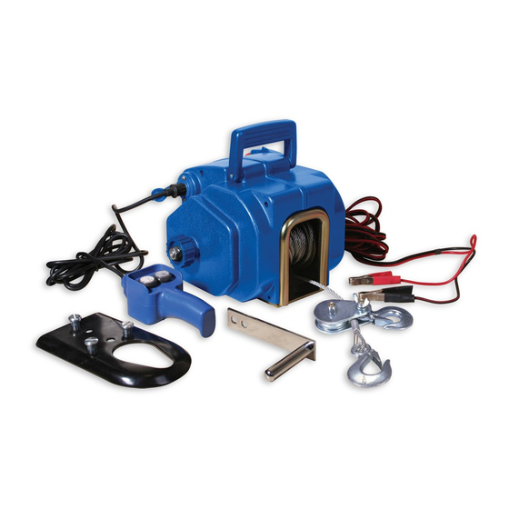
Page 2: Product Specifications
(GB) PRODUCT SPECIFICATIONS Model Rolling Load Marine Power Draw Cable N.W. Capacity Capacity Specs. Single Double Max. Max. Power Circuit Cable Cable Line Line Boat Boat Supply Breaker Length Diameter Weight Length volt 3,000 U0705 5,000 2,000 25±3 18.2 OWNER’S RESPONSIBILITY 1. - Page 3 W ARNING Never use as a lifting device or as a hoist for vertical lifting (see Figure1). Never winch a vehicle with passengers in it, leaning against it, or pushing it from behind (see Figure 2). All performance ratings are based on the first layer of the cable on the spool with no less than 5 full turns.
-
Page 4: Assembly Instruction
ASSEMBLY INSTRUCTION Permanent Mounting Of The Winch: 1. Select a mounting site on the bed of a truk, trailer, or other suitable location. 2. Align the Base of the Winch with the desired location, and mark for drilling the three mounting holes required to attach the Winch to the desired location. Then, drill these three mounting holes on the vehicle/trailer. - Page 5 Temporary Mounting of the Winch: 1. Insert three Screws (part# 74) into the three mounting holes in the Adapter Plate, and secure the Screws to the Adapter Plate, using three Washers (part# 76), and three Nuts (part# 77). (See Figure B.) 2.
- Page 6 To Connect the Electrical Wiring: NOTICE: The use of an “Overload Protection Device” (circuit breaker) is highly recommended in order to protect the vehicle and its battery from damage in case of a winch failure/overload. A 30 - amp circuit breaker (not included) should be purchased and installed in a safe location as close to the vehicle’s battery as possible.
- Page 7 6. WARNING: Never continue using the Winch until the vehicle’s 12 Volt DC Battery is run down. You may wish to keep the engine running while using the Winch to continually recharge the Battery. However, make sure the vehicle is in” neutral,” the vehicle’s emergency brake has been set and, whenever possible, the vechicle’s wheels have been chocked.
- Page 8 To Attach The Hand Crack: 1. Insert the mounting hole of the Hand Crank (part# 1) onto the Shaft (part# 21). Then secure the Hand Crank to the Shaft, using one Nut (part# 24). (See Figure HAND CRANK (#1) SHAFT (#21) NUT (#24) STEEL CABLE FIGURE E...
- Page 9 To Use The Electrically Powered W inch: 1. If screw off Control Knob B (Part#43), you can pull out steel rope by hand quickly. In addition, we must ensure screw down Control Knob A (Part#32) and Control Knob B (Part#43) 2.
- Page 10 T o Use The Pulley Block: 1. With the Winch Cable Hook (Part# 57) and the accessory Pulley Block Assembly (part# 56) attached to the Steel Cable, the Pulley Block Assembly (part# 56) can be used to nearly double the Winch’s capacity by simply attaching the Pulley Block Assembly (part# 56) directly to the load and the Winch Cable Hook (part# 57) to a sturdy mount near the Winch (such as the rear bumper).
-
Page 11: Maintenance
It is recommended to have an annual inspection of the winch done by a local service center and that any defective parts be replaced with genuine Shinn Fu parts. 1. Lubricate the cable occasionally, or more often when used frequently. -
Page 12: Spezifikation
Spezifikation Modell Roll Last N.W. Boot Vermögen Zugkraft Kabelspez. Vermögen Max. M a x . Doppeltes Gewicht Versorgung Sicherung Länge Durchmesser Einfaches Länge Kabel Kabel Bootes 3,000 U0705 5,000 2,000 25±3 18.2 VERANTWORTLICHKEIT DES EIGENTÜMERS 1. Der Eigentümer und/oder der Benutzer muß diese Bedienungsan-leitung und die folgenden Warnungen kennen bevor die elektrische Winde in Gebrauch genommen wird. - Page 13 WARNUNG 1. Benutzen Sie die Seilwinde nie wie ein Takel für vertikales Heben. (siehe Abbildung 2. Ziehen Sie nie einen Wagen mit Insassen, nie gegen lehnen, oder schieben von der Hinterseite (siehe Abbildung 2). 3. Alle angegebenen Daten beziehen sich auf die erste Lage des Seils mit nicht weniger als mindestens drei Umdrehungen.
- Page 14 Abbildung 4 Abbildung 5 Montage der Winde D i e W i n d e i s t d a f ü r a u s g e l e g t , z e i t w e i s e u n t e r N u t z u n g d e r Befestigungsvorrichtung für die Anhängerkupplung montiert zu werden.
- Page 15 Installation Verkabelung der Elektrowinde Die Winde kann zeitweise oder dauerhaft verkabelt werden: Zeitweise Verkabelung 1 Die Gummidichtung anheben, und die Buchse des Kabels an den Stecker auf der rechten Seite des Windenkörpers anstecken. Dieser Stecker ist mit "Power" (Strom) gekennzeichnet. Das Kabel von der Winde zur Batterie verlegen und dabei darauf achten, dass es nicht in sich bewegende Teile gerät oder eine Stolpergefahr darstellt.
- Page 16 ACHTUNG! 1 Immer rot mit rot (positiv mit positiv) und schwarz mit dem Rahmen - als Verbindung zur Masse - verbinden, wenn die Batterie des eigenen Fahrzeuges als Stromquelle genutzt wird. 2 Nie die Winde oder anderes Zubehör so lange benutzen, dass die Batterie völlig entladen wird.
-
Page 17: Wartung
Einsatz der Handkurbel Warnhinweis: Die Kurbel nicht zur Unterstützung der in Betrieb befindlichen Winde benutzen. Es besteht Verletzungsgefahr, und die Winde kann beschädigt werden. 1 Das Ende der Handkurbel auf das flache Ende der mit einem Gewinde versehenen Welle an der linken Seite der Winde aufstecken und mittels der bereits aufgedrehten Mutter befestigen. -
Page 18: Spare Part Lists
Spare Part Lists U0705 Model Nr. U0705-WHA Wire Harness Assembly U0705-PL Plate U0705-HRC Handheld Remote Control U0705-WCH Winch Cable Hook U0705-HC Hand Crank U0705-MT Motor U0705-GS4 Gear set 4 U0705-GS2 Gear set 2 U0705-GS1 U0705-GS3 Gear set 1 Gear set 3... - Page 19 Ersatzteile-liste U0705 Modell Nr. U0705-WHA Drahtkabelstrang U0675-PL Platte U0675-HRC Fernbedienung U0705-WCH Kabelhaken U0705-HC Handkurbel U0705-MT Motor U0705-GS4 Radsatz 4 U0705-GS2 Radsatz 2 U0705-GS1 U0705-GS3 Radsatz 1 Radsatz 3...
- Page 20 Assembly Diagram Montage Darstellung Model Nr. U0705 Modell Nr. NOTE: Some parts are listed and --shown for illustration purposes only, and are not available individually as replacement parts. Anmerkung: Nicht alle Bestandteile der Winde sind Ersatzteile, aber sie werden in der auseinandergezogenen Darstellung als Bezugspunkt für die richtige Positionierung ausgezeigt.
- Page 21 Parts List Einzelteile-liste Model Nr. U0705 Modell Nr. Part # Description Part # Description Bezeichnung Teile-Nr Teile-Nr Bezeichnung Nut / Mutter M 12 Spacer / Distanzscheibe ∅ 12 Washer / Scheibe Drive Gear / Antriebszahnrad ∅ 42 Retaining Ring / Seegerring Spacer (2) / Distanzscheibe (2) Bearing / Wellenlager ∅...
- Page 22 DÉCLARATION DE CONFORMITÉ Conformément à la directive CE “EMC”, le soussigné, étant mandataire de Shinn Fu Europe B.V., Roosendaal, Pays-Bas, déclare à la responsabilité exclusive de la firme mentionnée ci-dessus que les modèles ont énuméré ci-dessous et sa variante proches pour lesquels vaut cette déclaration, répondent aux exigences de sécurité...
Need help?
Do you have a question about the fantom U0705 and is the answer not in the manual?
Questions and answers