Advertisement
Verwendungsbereich: Die thermisch gesteuerte Si-
cherheitseinrichtung 5067 dient zur temperaturseitigen
Absicherung von Heizkesseln in geschlossenen Heizungs-
anlagen, die mit festen Brennstoffen befeuert werden und
nicht mit einer eingebauten Durchflußbatterie oder einem
ungesteuerten, entsprechend dimensionierten Wasserer-
wärmer ausgestattet sind. Durch den Einsatz der Sicher-
heitseinrichtung können auch bereits installierte Kessel
ohne eingebauten Wassererwärmer nachträglich für die
Verwendung von festen Brennstoffen umgerüstet werden.
Zakres stosowania: Zabezpieczenie termiczne instalacji
5067 służy do obniżania temperatury kotła w otwartych i
zamkniętych instalacjach grzewczych, które ogrzewane
są paliwami stałymi i nie mają wbudowanego wymiennika
chłodzącego.
Field of application: The thermal safety combination
type 5067 prevents excess temperatures in solid fuel fired
boilers, in unvented heating installations without integral
heat exchanger or hot water storage vessels. This protec-
tive device can be retrofitted to solid fuel boilers without
integrated hot water storage vessels.
2
3
1
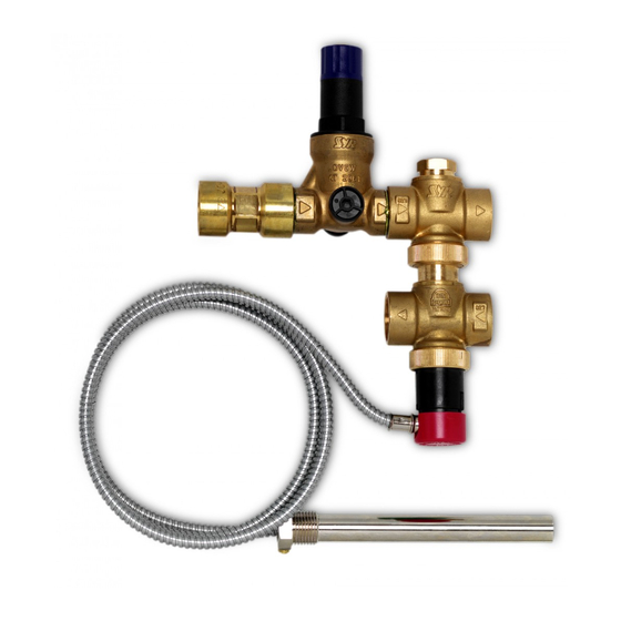
Einbau und Funktion: Die Sicherheitseinrichtung be-
inhaltet, in Fließrichtung, die folgenden Bauelemente:
Rückflußverhinderer (1), Druckminderer (2), thermisch
gesteuertes Eingangsventil (öffnet 92°C, schließt 87°C)
(3), thermisch gesteuertes Ausgangsventil (öffnet 99°C,
schließt 94°C) (4), Temperaturfühler (5).
Die Eingangsseite der Sicherheitseinrichtung (a) wird mit
dem Wasserversorgungsnetz verbunden. Die Ausgangs-
seite des Eingangsventils (b) führt zum Kesselrücklauf des
Heizkessels. Die Kesselvorlaufleitung (c) wird mit dem
Ausgangsventil der Sicherheitseinrichtung verbunden.
Dessen Ausgangsseite (d) führt über den eingebauten
Ablauf-trichter zu einer Entwässerung.
Instalacja i działanie: Zawór zabezpieczenia termiczne-
go 5067 składa się z następujących części (patrząc w kie-
runku przepływu): zawór zwrotny (1), reduktor ciśnienia (2),
sterowany termicznie zawór napełniający (3) (otwarcie
w 92
C, zamknięcie w 87
o
wyrzutowy (4) (otwarcie w 99
czujnik temperatury z kapilarą (5).
Wejście sterowanego termicznie zaworu 5067 (a) jest
połączone z siecią wodną, wyjście sterowanego termi-
cznie zaworu napełniającego (b) podłączone jest do prze-
wodu powrotnego kotła. Przewód zasilający kotła do
wejścia sterowanego termicznie zaworu wyrzutowego (c).
Wyjście zaworu wyrzutowego (d) jest prowadzone do
odpływu.
Installation and function: The thermal safety combination
includes the following components (in direction of flow):
check valve (1), pressure reducing valve (2), temperature
activated inlet valve (opens at 92°C, closes at 87°C) (3),
temperature activated outlet valve (opens at 99°C, closes
at 94°C) (4), temperature probe (5).
Connect the inlet of the thermal safety combination (a) to
5
the water supply. The outlet of the inlet valve (b) leads to
the heating return line. Connect the radiator supply line (c)
4
to the outlet valve of the thermal safety combination. The
outlet of the inlet valve (d) leads through the integrated
tundish to the drain .
1232 - Printed in Germany
C), sterowany termicznie zawór
o
C, zamknięcie w 94
C),
o
o
9.5067.00
Der Temperaturfühler ist an der heißesten Stelle, vor-
zugsweise im Oberboden des Kessels, zu montieren. Für
einwandfreie Temperaturmessung darf nur die mitgelieferte
Tauchhülse verwendet werden. Der Druckminderer muß
auf einen Druck eingestellt werden, der unterhalb des
höchstzulässigen Betriebsdrucks der Heizungsanlage
liegt. Hierdurch wird ein Ansprechen des in jedem Fall zur
druckseitigen Absicherung des Heizkessels notwendigen
Membransicherheitsventils vermieden.
Czujnik temperatury montuje się w najcieplejszym miej-
scu, najlepiej w górnej części kotła. Można używać
wyłącznie oryginalnej - fabrycznej tulei zanurzeniowej,
aby otrzymać właściwe pomiary temperatury.
Nastawa ciśnienia na reduktorze powinna być poniżej
maksymalnego dopuszczalnego ciśnienia pracy in-
stalacji grzewczej, aby uniknąć zadziałania zaworu
bezpieczeństwa (instalacja zamknięta). Konieczne jest
zastosowanie zaworu bezpieczeństwa, aby zabezpieczyć
przed przekroczeniem maksymalnego ciśnienia pracy
Install the temperature probe at the hottest spot, preferably
in the upper part of the boiler. Only use the immersion
sleeve enclosed in the delivery to ensure correct tempera-
ture measurements. Set the pressure reducing valve to a
pressure below the highest admissible operating pressure
of the heating system in order to prevent a response of
the diaphragm pressure relief valve, which is imperatively
required for the protection of the boiler against excess
pressure.
(a)
(b)
(c)
(d)
Advertisement
Table of Contents

Related Manuals for SYR 5067

Summary of Contents for SYR 5067
- Page 1 Instalacja i działanie: Zawór zabezpieczenia termiczne- 5067 służy do obniżania temperatury kotła w otwartych i stalacji grzewczej, aby uniknąć zadziałania zaworu go 5067 składa się z następujących części (patrząc w kie- zamkniętych instalacjach grzewczych, które ogrzewane bezpieczeństwa (instalacja zamknięta). Konieczne jest runku przepływu): zawór zwrotny (1), reduktor ciśnienia (2),...
- Page 2 C zostaje zamknięty zawór wyrzutowy. Dzięki reduktorowi ciśnienia w zaworze napełniającym i otwartemu zaworowi wejściowemu w za- worze 5067, instalacja grzewcza ma zapewnione właściwe ciśnienie pracy. Kiedy kocioł osiąga temperaturę 87 zamyka się również zawór napełniający. When the temperature exceeds the set response tem- perature, the following operational sequence is started: The seat of the inlet valve opens at a temperature of 92°C...
Need help?
Do you have a question about the 5067 and is the answer not in the manual?
Questions and answers