Table of Contents
Advertisement
Quick Links
V A N T A G E C O N T R O L S . C O M
2168 West Grove Parkway, Suite 300, Pleasant Grove, UT. 84062 USA
● Telephone: 801 229-2800 ● Fax: 801 224-0355
Overview
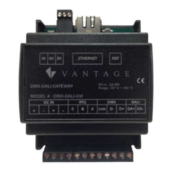
The Vantage DMX DALI GATEWAY
(DDG)
simultaneously
information to/from DMX and/or DALI
devices. The DDG station provides a
full DMX universe of 512 channels, from
which 64 channels may be used for
DALI
control.
The
information
transmitted via Ethernet, in controlled
packets, to the Vantage Controller
which acts as the central control point.
The
Vantage
Controller
transmits controlled packets back to the DDG to be distributed
to each connected bus. The Vantage controller manages the
information, load status and levels; making the interface simple
to use.
This product is very versatile and its capabilities and limits must
be fully understood to use effectively. Read all of these
instructions before installing.
DMX DALI GATEWAY Features/Operations
Standard RJ45 Ethernet terminal connector
Phoenix type screw terminals
o Easy power and bus connections
4-LED Communication Status Indicators
o Ethernet, Bus 1, Bus 2, and Bus 3
Firmware Updateable*
Support for DMX and/or DALI devices simultaneously
o Bus 2 is DMX
o Bus 3 is DALI
Reset Button
o Boot Loader Mode: Standard Press & Release, do not
hold – ...
Reboots station into boot loader mode, LEDs may
flicker and then go off.
Boot
loader
mode
firmware.
Re-power the station to exit boot loader mode.
o Factory Reset: Press and hold just over 4 seconds – ...
Resetting to factory settings - LEDs go off until the
station reboots to factory settings - all load
channels are set back to default.
This also resets the IP address to factory settings.
Reference Standards
o IEC 61547.
Equipment for general lighting purposes – EMC immunity
requirements
o IEC 61000-3-2
Electromagnetic compatibility (EMC) – Part 3-2: Limits –
Limits for harmonic current emissions (equipment input
current
16A per phase)
o EN 55015
Limits and methods of measurement of radio disturbance
characteristics of electrical lighting and similar equipment
o IEC/EN 62386-101
Digital addressable lighting interface – Part 101: General
requirements - System
o IEC/EN 62386-102
Digital addressable lighting interface – Part 102: General
requirements – Control gear
o IEC/EN 62386-207
Digital addressable lighting interface – Part 207: Particular
requirements for control gear – LED modules (device type
6)
o ANSI E 1.3
Entertainment Technology – Lighting Control Systems – 0
to 10V Analog Control Specification
o ANSI E 1.11
Entertainment
Technology
Asynchronous Serial Digital Data Transmission Standard
for Controlling Lighting Equipment and Accessories
o ANSI E 1.20
Entertainment
Management over USITT DMX512 Networks – Lighting
Control Systems – 0 to 10V Analog Control Specification
©Vantage, 8/1/2016 / IS-00703-C
processes
is
conversely
is
used
when
upgrading
–
USITT
DMX512-A
Technology-RDM-REMOTE
Vantage DMX DALI Gateway – MODEL: DMX-DALI-GW
Vantage DMX DALI Gateway – MODEL: DMX-DALI-GW
System Specifications
Description
Dimensions, HWD
Weight
Input Voltage
Mounting
Connects to Vantage Via
Maximum Power Draw
Minimum Power Draw
Max. DDG Loads (channels)
ModBus RTU Bus 1
DMX Bus 2, full DMX universe
Support for NSC, SIP, RDM
DALI Bus 3
DMX / DALI Channels
DALI Groups 1-16
4-LED Communication
Status Indicators
Local Contact (n.o.) input
Ambient Operating Temperature
Ambient Operating Humidity
CE Certified
*Firmware Update
Before installing the Vantage DDG, make sure the firmware has
been updated to the latest release. See Steps to Update
Station Firmware on page 5 in this document. After a firmware
update the station's new factory setting IP address is
192.168.1.225. However, updating firmware does not change the
IP address to the factory setting. Only a factory reset will
change the IP address to the factory setting – see Reset Button
(previous column).
**Setting ModBus RTU, Bus 1 to DMX
It is possible, through the DGM Device Config tool, to set the
ModBus RTU, Bus 1 to DMX512. Setting the ModBus RTU, Bus 1
to DMX512 only mirrors Bus 2 on the InFusion System. Design
Center only supports one DMX512 universe on each DDG
station and cannot distinguish between Bus 1 and Bus 2 on the
same station. Sending a command to any DMX channel will
simultaneously control loads assigned to that channel number
on both Bus 1 and Bus 2 DMX universes.
DMX-DALI-GATEWAY / DGM Configuration Steps
The DGM Configuration software is built-in the DDG station
and is accessed by connecting to the station's IP address via
most internet browsers.
NOTE: The DGM Config tool has to connect to the DDG station
via the default IP address when the station is in default mode
or an assigned IP address if the station is not in default mode
and has been assigned a new IP address. The steps below may
require the default IP address of 192.168.1.225 be substituted
with 192.168.1.4 -or- if the station has previously been assigned
a new IP address, and is not in default mode, substitute the
new IP address.
Power on the station with the correct power supply.
1.
The station comes with a static IP Address of 192.168.1.225
or 192.168.1.4. The 192.168.1.225 IP address is from newer
firmware releases.
2. Follow the a. or b. steps below depending on the local
network.
–
Section
a. If the local network is not on the 192.168.1.x subnet and
a
the DDG station is set to default mode:
Device
i.
Configure the local network's router to reserve a
static IP address for the DDG station – record for later
use.
ii.
Disconnect the computer from the main network.
I N S T A L L A T I O N
V A N T A G E I N S T A L L G U I D E S
Specification
3.5" x 2.8" x 2.4"
90mm x 72mm x 62mm
4.8oz - 136g
12Vdc | 320mA – 48Vdc | 80mA
35 mm DIN Rail (EN 50 022: 1977)
Ethernet, RJ45 – 10/100Mbit
RTU MODBUS (not supported**)
512 DMX channels – NSC, SIP, RDM
NSC
–
Null Start Code
SIP
– System Information Packet
RDM – Remote Device Management
64 channels, 125mA power supply
Duplicate DMX and DALI channel assignments
are shared on both buses
Control from 1 to 16 DALI groups
(see Using DALI Groups, pg5)
1 LED for each:
Ethernet, Bus 1, Bus 2, and Bus 3
Stand-alone mode, not used with InFusion
min. -40°C to max. 40°C
min. -40°F to max. 140°F
non-condensing environment
500mA
40mA
512
application
YES
page 1 of 6
Advertisement
Table of Contents

Summary of Contents for Vantage Hearth DMX-DALI-GW
- Page 1 V A N T A G E I N S T A L L G U I D E S 2168 West Grove Parkway, Suite 300, Pleasant Grove, UT. 84062 USA Vantage DMX DALI Gateway – MODEL: DMX-DALI-GW ● Telephone: 801 229-2800 ● Fax: 801 224-0355...
- Page 2 Select Bus 2 and change to Slave mode, exit back to DGM Configuration tool. home page and save. Repeat for Bus 3 – see figure 2. Installation ©Vantage, 8/1/2016 / IS-00703-C Vantage DMX DALI Gateway – MODEL: DMX-DALI-GW page 2 of 6...
- Page 3 DALI channel to avoid overlapping channels. from Design Center tasks or the Equinox lighting widget. Be aware that DALI channels may be assigned an offset Adding Color Loads ©Vantage, 8/1/2016 / IS-00703-C Vantage DMX DALI Gateway – MODEL: DMX-DALI-GW page 3 of 6...
- Page 4 * The Equinox lighting widget also allows load presets to be saved. Saved Presets only save the light level not the preset color values at this time. ©Vantage, 8/1/2016 / IS-00703-C Vantage DMX DALI Gateway – MODEL: DMX-DALI-GW page 4 of 6...
- Page 5 The tool also allows global settings for the DALI BUS reassign all the loads to the same new address. as covered in the previous column. ©Vantage, 8/1/2016 / IS-00703-C Vantage DMX DALI Gateway – MODEL: DMX-DALI-GW page 5 of 6...
- Page 6 Design Center, may flicker and then go off o The station is now ready for the new firmware to be downloaded. DMX-DALI-GW Line Drawings ©Vantage, 8/1/2016 / IS-00703-C Vantage DMX DALI Gateway – MODEL: DMX-DALI-GW page 6 of 6...
Need help?
Do you have a question about the DMX-DALI-GW and is the answer not in the manual?
Questions and answers