
Subscribe to Our Youtube Channel
Summary of Contents for Holtek ESK32-A3A31
- Page 1 ESK32-A3A31 33 SEG × 8 COM Monochrome LCD User Manual Revision: V1.00 Date: October 27, 2020...
-
Page 2: Table Of Contents
2.1 ESK32-A3A31 Expansion Board Connector – CN1 ...............9 2.2 ESK32-A3A31 Expansion Board Connector – CN2 ...............9 2.3 ESK32-A3A31 LCD 33 × 8 Connector – CN3 ..............10 2.4 ESK32-A3A31 Segment Switch – SW1, SW2 ..............11 2.5 ESK32-A3A31 LCD Map ...................... 11 3. -
Page 3: Overview
In the user manual the Starter Kit takes the ESK32-30511 as an example. The HT32F57352 is used as a target MCU for the ESK32-30511. Users can connect the ESK32-A3A31 monochrome LCD panel to the ESK32-2x001A expansion board and use it with the ESK32-30511 Starter Kit. This will help users speed up development and verify the application. -
Page 4: Esk32-2X001A Introduction
ESK32-A3A31 33 SEG × 8 COM Monochrome LCD User Manual 1.2 ESK32-2x001A Introduction The HT32 provides two expansion boards, ESK32-20001A and ESK32-21001A, also equipped with rich peripheral accessories to easy for users to evaluate the functions and features of HT32 MCU. - Page 5 ESK32-A3A31 33 SEG × 8 COM Monochrome LCD User Manual Figure 3. ESK32-30511 (Front) Figure 4. ESK32-30511 (Back) Rev. 1.00 October 27, 2020...
- Page 6 ESK32-A3A31 33 SEG × 8 COM Monochrome LCD User Manual Pin No. Description Pin No. Description S_BCLK (see Table 9, Opt2-1) PA9 / I S_WS / RS232_TX (connect to MCU TX) PA4 / RS232_RX (connect to MCU TX) (see J2, DAP_TX)
- Page 7 ESK32-A3A31 33 SEG × 8 COM Monochrome LCD User Manual Pin No. Description Pin No. Description 3.3V 3.3V PA1 / I S_SDA PA0 / I S_SCL S_SDO (see Table 9, Opt2-2) PD10 S_SDI (see Table 9, Opt2-3) PA9 / BOOT1...
-
Page 8: Hardware Description
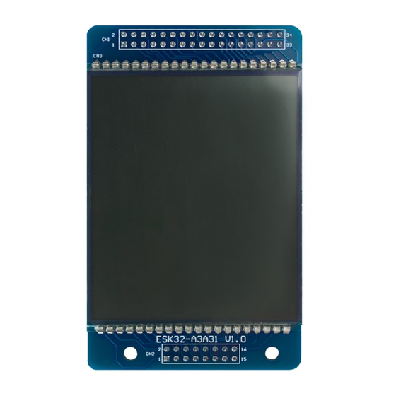
The ESK32-A3A31 is a 33 SEG × 8 COM monochrome LCD panel for the HT32 series expansion board. The front view of ESK32-A3A31 Layout is shown in the Figure 5. The back view of ESK32- A3A31 Layout is shown in the Figure 6. -
Page 9: Esk32-A3A31 Expansion Board Connector - Cn1
Figure 7. Expansion Board Connector CN1 (ESK32-A3A31) Pin No. Description Pin No. Description Table 3. Pin Assignment for Expansion Board Connector CN1 (ESK32-A3A31) 2.2 ESK32-A3A31 Expansion Board Connector – CN2 Figure 8. Expansion Board Connector CN2 (ESK32-A3A31) Pin No. Description Pin No. -
Page 10: Esk32-A3A31 Lcd 33 × 8 Connector - Cn3
S5 / SEG6 S4 / SEG5 S3 / SEG4 S2 / SEG3 S1 / SEG2 S0 / SEG1 # : mean the specific Switch settings. Table 5. Pin Assignment for LCD 8 × 33 Connector CN3 (ESK32-A3A31) Rev. 1.00 October 27, 2020... -
Page 11: Esk32-A3A31 Segment Switch - Sw1, Sw2
ESK32-A3A31 33 SEG × 8 COM Monochrome LCD User Manual 2.4 ESK32-A3A31 Segment Switch – SW1, SW2 MCU can select an unused LCD Segment to output dummy signal and connect the rest of the unused LCD Segment through SW1 and SW2 to avoid ghost phenomenon and affect the display effect. - Page 12 ESK32-A3A31 33 SEG × 8 COM Monochrome LCD User Manual 57352 M_S4 M_S16 2x001A Board SEG4 SEG5 M_C1 COM2 BT-D M_C4 PC10 COM3 BT-U Figure 11. Bluetooth Display (ESK32-A3A31) 57352 M_S3 M_S4 M_S16 M_S17 2x001A Board SEG3 SEG4 SEG5 SEG6...
- Page 13 ESK32-A3A31 33 SEG × 8 COM Monochrome LCD User Manual 57352 M_S5 2x001A Board SEG13 M_C0 PB15 COM1 M_C1 COM2 BAT1 M_C4 PC10 COM3 BAT2 M_C3 PA10 COM8 BAT3 Figure 13. Battery Display (ESK32-A3A31) 57352 M_S17 2x001A Board SEG6 M_C2...
- Page 14 M_C1 COM2 Time M_C4 PC10 COM3 M_C3 PA10 COM8 Dot3 Dot2 Dot1 Figure 15. 7-Segment Group 1 Display (ESK32-A3A31) 57352 M_S1 M_S2 M_S3 M_S4 M_S16 M_S18 M_S19 M_S20 M_S21 M_S22 M_S23 M_S5 PA14 PA15 PD11 PD12 PD13 PD14 PD15 2x001A...
- Page 15 M6-12 M6-13 M6-14 M6-15 M6-16 M6-17 M6-18 M6-19 M6-20 M_C2 COM7 M5-11 M5-12 M5-13 M5-14 M5-15 M5-16 M5-17 M5-18 M5-19 M5-20 M_C3 PA10 COM8 M4-11 M4-12 M4-13 M4-14 M4-15 M4-16 M4-17 M4-18 M4-19 M4-20 Figure 17. 20 × 8 Martix Display (ESK32-A3A31) Rev. 1.00 October 27, 2020...
-
Page 16: Using The Lcd Panel
ESK32-A3A31 33 SEG × 8 COM Monochrome LCD User Manual 3. Using the LCD Panel 3.1 Tool Preparation Users need to prepare the HT32 Series Expansion Board (ESK32-20001A / ESK32-21001A) and the HT32F573xx Starter Kit (ESK32-30511 / ESK32-30512). 3.2 LCD Panel Setting Before using the LCD Panel, please refer to Table 5 for the LCD settings details. -
Page 17: Starter Kit Setting - Using The Ht32F57352 Starter Kit As An Example
ESK32-A3A31 33 SEG × 8 COM Monochrome LCD User Manual 3.4 Starter Kit Setting – using the HT32F57352 Starter Kit as an example Users can refer to Table 9 for the starter kit settings associated with the LCD panel. Refer to the “HT32 MCU Starter Kit User Manual”... -
Page 18: Board Assembly
× 8 COM LCD panel (ESK32-A3A31), as shown in Figure 19. Figure 19. HT32 Mono-LCD Development Kit 3.6 Obtain the Example Program Download the latest Holtek HT32 Firmware Library. The download web link is https://www.holtek. com/Development-Kit-software. Unzip the HT32 Firmware Library after downloading. 3.7 Compile and Execute the Program To execute the Mono_LCD example, the Keil MDK-ARM or IAR EWARM need to setup. -
Page 19: Schematics
ESK32-A3A31 33 SEG × 8 COM Monochrome LCD User Manual 4. Schematics This section shows the HT32 Mono-LCD circuitry. SEG1 SEG14 / Matrix X 1 SEG2 SEG15 / Matrix X 2 SEG3 SEG16 / Matrix X 3 SEG4 SEG17 / Matrix X 4... -
Page 20: Disclaimer
Information displayed at such sites. Hyperlinks to other websites are at your own risk. Limitation of Liability In no event shall Holtek Limited be liable to any other party for any loss or damage whatsoever or howsoever caused directly or indirectly in connection with your access to or use of this website, the content thereon or any goods, materials or services. - Page 21 However, Holtek assumes no responsibility arising from the use of the specifications described. The applications mentioned herein are used solely for the purpose of illustration and Holtek makes no warranty or representation that such applications will be suitable without further modification, nor recommends the use of its products for application that may present a risk to human life due to malfunction or otherwise.
Need help?
Do you have a question about the ESK32-A3A31 and is the answer not in the manual?
Questions and answers