Table of Contents
Advertisement
Quick Links
Advertisement
Table of Contents

Related Manuals for METER ES-2


Summary of Contents for METER ES-2
- Page 1 ES-2...
-
Page 2: Table Of Contents
2. Operation ....................2 2.1 Installation ....................2 2.2 Connecting ....................3 2.2.1 Connect to METER Data Logger ............4 2.2.2 Connect to a Non-METER Data Logger ..........4 2.3 Communication ..................6 3. System ......................7 3.1 Specifications .................... 7 3.2 Components .................... -
Page 4: Introduction
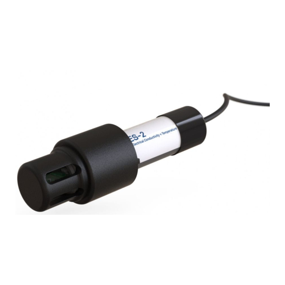
Thank you for choosing the ES-2 Electrical Conductivity and Temperature Sensor from METER Group. The ES-2 sensor measures in an irrigation pipe, a water body, or in a tank. A thermistor in thermal contact with the probe provides water temperature, while the screws on the surface of the sensor from a four-electrode array to measure electrical conductivity (EC). -
Page 5: Operation
OpERATION 2. OpERATION Please read all instructions before operating the ES-2 to ensure it performs to its full potential. pRECAUTIONS METER sensors are built to the highest standards, but misuse, improper protection, or improper installation may damage the sensor and possibly void the manufacturer’s warranty. -
Page 6: Connecting
For more instructions on connecting to data loggers, refer to Section 2.2. 2.2 CONNECTING The ES-2 works seamlessly with METER data loggers. The ES-2 can also be used with other data loggers, such as those from Campbell Scientific, Inc. For extensive directions on how to... -
Page 7: Connect To Meter Data Logger
Power Figure 1 Stereo plug connector The ES-2 comes standard with a 5-m cable. It may be purchased with custom cable lengths for an additional fee (on a per-meter basis). In some instances, the cable can be extended beyond 75 m by the user, but this is discouraged for a variety of reasons. Please contact... - Page 8 Ground (bare) Digital communication (orange) Figure 2 pigtail wiring NOTE: Some early ES-2 units may have the older Decagon wiring scheme where the power supply is white, the digital out is red, and the bare wire is ground. Digital Power communication...
-
Page 9: Communication
ES-2 Integrator Guide. The SDI-12 protocol requires that all sensors have a unique address. ES-2 sensor factory default is an SDI-12 address of 0. To add more than one SDI-12 sensor to a bus, the sensor address must be changed as described in these steps. -
Page 10: System
±0.01 dS/m or ±10% (whichever is greater) COMMUNICATION SpECIFICATIONS Output DDI serial or SDI-12 communication protocol Data Logger Compatibility METER ZL6 data loggers and any data acquisition system capable of 3.6- to 15-VDC power and serial or SDI-12 communication pHYSICAL SpECIFICATIONS Dimensions Length 10.9 cm (4.30 in) - Page 11 SYSTEM Cable Length 5 m (standard) 75 m (maximum custom cable length) NOTE: Contact Customer Support if a nonstandard cable length is needed. Connector Types 3.5-mm stereo plug connector or stripped and tinned wires ELECTRICAL AND TIMING CHARACTERISTICS Supply Voltage (VCC to GND) Minimum 3.6 V Typical...
-
Page 12: Components
EM ISO/IEC 17050:2010 (CE Mark) 3.2 COMpONENTS Thes ES-2 uses four stainless steel electrodes for its conductivity measurement, which is less sensitive to contamination than a two electrode sensor (Figure 4). A thermistor in contact with the probe provides water temperature. A protective cap helps protect the electrodes from damage and contamination, and a small plug can be added or removed, depending on the installation application. -
Page 13: Theory
ES-2 sensor bulk EC measurements are corrected to EC at 25 °C: ⎡ ⎣ 1+ 0.019(T − 25) ⎤... -
Page 14: Service
Table 2 relates EC at 25 °C to concentration for various concentrations of KCl. Operators can verify ES-2 performance using these solutions. The ES-2 internally corrects output value to 25 °C. Table 2 EC of KCl solutions for testing ES-2 calibrations Electrical Conductivity (μS/cm) -
Page 15: Troubleshooting
Solutions If using a METER logger, update logger firmware. Data logger is not Check the logger configuration for a non-METER data logger using its recognizing sensor user manual. Check power to the sensor. Check that the connections to the data logger are both correct and secure. -
Page 16: Terms And Conditions
NOTE: For products purchased through a distributor, please contact the distributor directly for assistance. 4.5 TERMS AND CONDITIONS By using METER instruments and documentation, you agree to abide by the METER Group, Inc. USA Terms and Conditions. Please refer to metergroup.com/terms-conditions... -
Page 17: Index
11 physical 7–8 compliance 9 components 9–10 tank installation 3 connecting temperature 1, 7, 9, 10 METER data logger 4 terms and conditions 13 non-METER logger 4–5 theory 10 connector types 8 customer support 12–13 troubleshooting 12 electrical conductivity 1, 9, 10, 11... - Page 18 14572-02 4.30.2020 METER Group, Inc. USA 2365 NE Hopkins Court Pullman, WA 99163 T: +1.509.332.2756 F: +1.509.332.5158 E: info@metergroup.com W: metergroup.com METER Group AG Mettlacher Straße 8, 81379 München T: +49 89 1266520 F: +49 89 12665220 E: info.europe@metergroup.com W: metergroup.de...
Need help?
Do you have a question about the ES-2 and is the answer not in the manual?
Questions and answers