
Summary of Contents for envea ProGap 2.0
- Page 1 OPERATING INSTRUCTIONS ProGap 2.0 LEVEL DETECTION ENVEA Process GmbH - Gutedelstraße 31 – 79418 Schliengen - GERMANY Tel.: +49 (0) 7635 827248-0 / info.process@envea.global / www.envea.global...
-
Page 2: Table Of Contents
CONTENTS Page General comment ..........3 Function . -
Page 3: General Comment
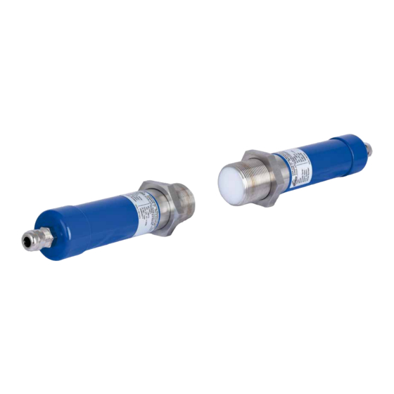
Fig. 1: Overview measuring point 2. Function The ProGap 2.0 is a non-contact microwave barrier. The sensor can be used on metallic and non-metallic pipes, tanks, manholes, bellows, etc. The microwave measure through non-conductive materials, such as plastics, glass, etc. This makes it possible to detect with the sensor from the outside or through a window. -
Page 4: Safety
3. Safety The ProGap 2.0 measuring system has a state of the art, reliable design. It was tested and found to be in a perfectly safe condition when leaving the factory. Nevertheless, the system components may present dangers to personnel and items if they are not operated correctly. -
Page 5: Mounting And Installation
4. Mounting and installation 4.1 A measuring point consists of the following components: 1 x Transmitter unit • 1 x Receiver unit • 2 x lock nut for locking transmitter and receiver unit • 2 x G-1½”-socket for mounting the unit •... -
Page 6: Electrical Connection
5. Electrical connection The cable length between power supply and transmitter / receiver system is a maximum of 200 m. A double insulated shielded cable with a minimum cross section of 0.75 mm² is recommended. From a cable length of 100 m, the cable cross-section must be increased to 1 mm². The transmitter / receiver system has an EMV cable gland. -
Page 7: Start-Up Procedure
6. Start-up procedure Before the ProGap 2.0 measuring point can be put into operation, the electrical connection should be checked. After the power supply has been switched on, a warm-up time of 5 minutes must be observed. All operating elements required for commissioning are located in the receiver. -
Page 8: Fault Clearance
Adjusting of the switch response time potentiometer P2 Adjust the switch response time with the potentiometer P2 according to your requirement between the range of 0.25 and 5 seconds. By turning P2 to left stop, the delay will be 0.25 seconds. At right stop the delay time will be 5 seconds. -
Page 9: Technical Data
K-Band 24.125 GHz / ± 100 MHz Transmitting power max. 5 mW Weight Transmitter 1.1 kg Receiver 1.1 kg ENVEA Process GmbH Gutedelstraße 31 · 79418 Schliengen (Germany) Fon +49 7635 827248-0 · Fax +49 7635 827248-48 · www.envea.global PART OF THE ENVEA GROUP DE 05/08/2020...
Need help?
Do you have a question about the ProGap 2.0 and is the answer not in the manual?
Questions and answers