
Related Manuals for Nuvation Energy Stack Switchgear

Summary of Contents for Nuvation Energy Stack Switchgear
- Page 1 Nuvation Energy Stack Switchgear Product Manual Document ID: NE-PM-003 | Revision: 1.0, 2020-09-03 © 2020 Nuvation Energy...
-
Page 2: Table Of Contents
2.1. Nuvation Energy Stack Switchgear ......... - Page 3 7. Using the Nuvation Energy BMS Operator Interface ....... .
- Page 4 .......... Appendix B: Changing the Nuvation Energy BMS Network Configuration ....
-
Page 5: Important Safety Information
The content in this document must be followed in order to ensure safe operation of Nuvation Energy BMS. Do NOT energize the system until all connections to the Stack Switchgear unit and Cell Interface modules have been made. The wiring of the battery cell voltage and temperature sensing should be verified before connecting to the Cell Interface modules. - Page 6 You must use proper electrical safety precautions when handling any part of Nuvation Energy BMS. Neither Nuvation Energy or any of its employees shall be liable for any direct, indirect, incidental, special, exemplary, personal or consequential harm or damages (including, but not limited to, procurement or substitute goods or ...
-
Page 7: Introduction
Nuvation Energy BMS to your specific target application. 1.1. About this Manual This Nuvation Energy Stack Switchgear: Product Manual provides mounting and wiring to connect your Nuvation Energy Stack Switchgear to your system as well as instructions on using the Nuvation Energy Stack Switchgear. ... -
Page 8: System Overview
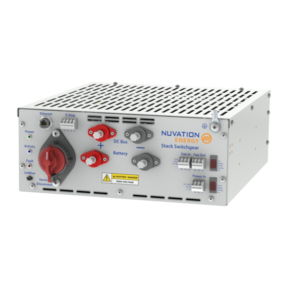
E-Stop. It also includes supporting components like power supplies, indicator LEDs, and external-facing connectors. Figure 1. Nuvation Energy Stack Switchgear There are different amperage configurations available for the base Stack Switchgear unit, listed in Table 1. Orderable part numbers are listed in Nuvation Energy Stack Switchgear: NUVSSG Datasheet, available online at https://www.nuvationenergy.com/technical-resources. - Page 9 3, each Stack Switchgear unit is responsible for monitoring the state and safety of one battery stack. All Stack Switchgear units connected to a single common DC bus in the system may be connected to a single Nuvation Energy Battery Control Panel, where an Operator Interface provides a unified view and central control of the multi-stack system.
- Page 10 Nuvation Energy Stack Switchgear - Product Manual Figure 3. Stack Switchgear multi-stack diagram Document ID: NE-PM-003 Rev 1.0, 2020-09-03...
-
Page 11: Nuvation Energy Stack Switchgear
2.1. Nuvation Energy Stack Switchgear 2.1.1. Mechanical Overview The Stack Switchgear is primarily designed to fit in a standard 19" rack with a 23"-deep cabinet. However, other mounting possibilities are supported, as the following subsections discuss. Depending on the desired application, brackets can be ordered with part numbers listed in Nuvation Energy Stack Switchgear: NUVSSG Datasheet, available online at https://www.nuvationenergy.com/... - Page 12 Nuvation Energy Stack Switchgear - Product Manual 2-Post Rack-Mount, 19" And 23" Brackets are available for 2-post open-frame racks. Mounting widths of 19" and 23" are supported, as shown in Figure 5 Figure 6, respectively. Note that third-party side-support 2-post-extension brackets are available, though not necessary.
- Page 13 Nuvation Energy Stack Switchgear - Product Manual Shelf-Mount A Stack Switchgear may also be mounted to the surface on which it rests, with the aid of shelf-mount brackets, as shown in Figure 7 Figure 7. Shelf-mount Dimensions This section provides detailed drawings of the Stack Switchgear and its mounting provisions.
- Page 14 Nuvation Energy Stack Switchgear - Product Manual Figure 8. Dimensions, overall Document ID: NE-PM-003 Rev 1.0, 2020-09-03...
- Page 15 Nuvation Energy Stack Switchgear - Product Manual Figure 9. Dimensions, rack-mount, 19" Document ID: NE-PM-003 Rev 1.0, 2020-09-03...
- Page 16 Nuvation Energy Stack Switchgear - Product Manual Figure 10. Dimensions, shelf-mount Document ID: NE-PM-003 Rev 1.0, 2020-09-03...
- Page 17 Nuvation Energy Stack Switchgear - Product Manual Figure 11. Dimensions, 2-post rack-mount, 19" Document ID: NE-PM-003 Rev 1.0, 2020-09-03...
-
Page 18: Internal Hardware Overview
Nuvation Energy Stack Switchgear - Product Manual Figure 12. Dimensions, 2-post rack-mount, 23" 2.1.2. Internal Hardware Overview The Nuvation Energy Stack Switchgear internally includes the following major hardware components: ▪ Nuvation Energy High-Voltage Stack Controller ▪ Nuvation Energy High-Voltage Power Interface ▪... - Page 19 Pre-Charge Circuit The Stack Switchgear has a pre-charge circuit to ensure safe connection of its battery stack to the DC bus. The pre-charge circuit temporarily connects the stack to the DC bus through an appropriately sized power resistor.
-
Page 20: External Interfaces
The fuses interrupt a short circuit event; two of them are used to provide redundancy and to permit use of the Stack Switchgear with an ungrounded battery stack. A microswitch is used on each fuse so that the BMS can recognize blown fuses and issue a fault alert. - Page 21 Nuvation Energy Stack Switchgear - Product Manual Name Description Connected to Device TD_P Transmit differential pair positive External Equipment TD_N Transmit differential pair negative External Equipment RD_P Receive differential pair positive External Equipment NUL45 Unused; connected to Pin 5 and terminated External Equipment NUL45 Unused;...
- Page 22 Nuvation Energy Stack Switchgear - Product Manual Link Bus The Link Bus connector provides power and communication to the Cell Interface modules. The amount of current supplied by this connector is the sum of current consumed by all Cell Interface modules in the system.
- Page 23 Nuvation Energy Stack Switchgear - Product Manual Internal Power The default Stack Switchgear requires 100 V to 240 V AC power to be supplied from an external source. Power is connected via feed-through connectors on the front panel, as shown in Table 6.
- Page 24 Internally, the E-Stop input is connected to the safety relay coils while the E-Stop output is connected to the internal 24 V DC power supply. One Stack Switchgear unit’s E-Stop output is capable of driving the E-Stop inputs for up to two Stack Switchgear units (i.e. one other Stack Switchgear unit in addition to itself);...
- Page 25 Nuvation Energy Stack Switchgear - Product Manual Figure 14. E-Stop circuit (external supply) The signals are connected via feed-through connectors on the front panel, as shown in Table 7. To install a conductor, insert a tool (such as a small flat screwdriver) into the rectangular opening at the top of the connector.
- Page 26 Nuvation Energy Stack Switchgear - Product Manual Fan Control This feature gives the ability for the Stack Switchgear to control external AC or DC fans for cooling the battery cells. The fans are enabled by the BMS when battery cell temperatures exceed configurable thresholds.
- Page 27 Nuvation Energy Stack Switchgear - Product Manual Figure 15 provides the internal wiring implementation of the fan control parts shown above. Figure 15. Battery cooling fan control wiring diagram Document ID: NE-PM-003 Rev 1.0, 2020-09-03...
- Page 28 Nuvation Energy Stack Switchgear - Product Manual Battery Stack and DC Bus The front panel of the Stack Switchgear has four high power connectors, as illustrated by Table 9. Two of these are for the positive and negative terminals of the battery stack; the other two are for the connection to the DC bus (or a power conversion system in a single stack system).
- Page 29 Nuvation Energy Stack Switchgear - Product Manual Grounding Stud The SSG must be bonded to the rack or earth through a suitably sized conductor by NEC standards. From NFPA 70, Table 250.122, the wire size must be chosen based on the rating of the automatic...
-
Page 30: Nuvation Energy Cell Interface
It facilitates battery monitoring and control functionalities. In a Stack Switchgear, depending on battery stack size and count, one or more Cell Interface modules are used to convert and relay cell voltage and temperature readings digitally to the Stack Controller. - Page 31 Nuvation Energy Stack Switchgear - Product Manual enclosure has five metal walls, leaving the bottom of the unit fully exposed. It must be mounted to a metal bulkhead panel such that the panel covers the exposed bottom side. The NUV100-CI-12-1 and NUV100-CI-16-1 variants produce up to 24 W and 32 W, respectively, during cell balancing.
- Page 32 Nuvation Energy Stack Switchgear - Product Manual The Mounting Bracket kit assembly adds an extra 14.2 mm to the overall width of the Cell Interface module, bringing it from 104.4 mm to 118.6 mm. The kit assembly holds the module approximately 7 mm away from the inside lip of the DIN rail.
- Page 33 Nuvation Energy Stack Switchgear - Product Manual Figure 20. Mechanical Drawing of Cell Interface with DIN Enclosure (NRND) Document ID: NE-PM-003 Rev 1.0, 2020-09-03...
-
Page 34: Installation
2. Install the brackets on the Stack Switchgear. 3. Place the Stack Switchgear onto the installed side-support angle brackets. 4. Secure the Stack Switchgear to the rail of the rack using the brackets installed. For 2-post installations (i.e. using the NUVP-SSG-RB-19-2P or NUVP-SSG-RB-23-2P): 1. - Page 35 For instructions on connecting the Cell Interface modules to the battery, refer to Section 3.2. 6. Install the Link Bus cable between the Stack Switchgear and the first Cell Interface in the Link Bus chain. 7. Install the connection to the battery and the DC bus.
-
Page 36: Cell Interface Installation
Nuvation Energy Stack Switchgear - Product Manual 3.2. Cell Interface Installation 3.2.1. Electrical Connections The Cell Interface module has 4 connectors. Each connector is described in the following sections in detail. Link Out The Link Out connector provides power and communication to the Cell Interface modules above this Cell Interface. - Page 37 Nuvation Energy Stack Switchgear - Product Manual Table 11. Link Out: Molex Micro-Fit 3.0 Connector Molex 43025-0400 Manufacturer Molex Incorporated Housing 43025-0400 Housing material Nylon UL94V-0 Circuits Crimp terminal 43030-0002 Wire gauge range AWG20-24 stranded Table 12. Link Out Connector Pin Assignment...
- Page 38 Nuvation Energy Stack Switchgear - Product Manual Table 13. Link In: Molex Micro-Fit 3.0 Connector Molex 43025-0400 Manufacturer Molex Incorporated Housing 43025-0400 Housing material Nylon UL94V-0 Circuits Crimp terminal 43030-0002 Wire gauge range AWG20-24 stranded Table 14. Link In Connector Pin Assignment...
- Page 39 Nuvation Energy Stack Switchgear - Product Manual The wiring of the battery cell voltage and temperature sensing should be verified before connecting to the Cell Interface modules. The temperature sensing must be isolated from the cell voltage sensing. Although the Cell Interface includes protective circuitry to make it more resilient to brief wiring errors, the same circuitry can result in the battery cells being slowly discharged.
- Page 40 Nuvation Energy Stack Switchgear - Product Manual Connection Description Connected to Device CELL1 Cell 1 voltage sense Connect to positive terminal of the lowest cell (Cell 1) CELL3 Cell 3 voltage sense Connect to positive terminal of Cell 3 CELL5...
- Page 41 Nuvation Energy Stack Switchgear - Product Manual Figure 21. Example wiring 12 cells in a Cell Interface - 12 channel Document ID: NE-PM-003 Rev 1.0, 2020-09-03...
- Page 42 Nuvation Energy Stack Switchgear - Product Manual Figure 22. Example wiring 8 cells in a Cell Interface - 12 channel Battery Cell Connector for Cell Interface - 16 channel Table 17. Cell Interface - 16 channel Battery Cell Connector Pin Assignment...
- Page 43 Nuvation Energy Stack Switchgear - Product Manual Connection Description Connected to Device CELL4 Cell 4 voltage sense Connect to positive terminal of Cell 4 CELL6 Cell 6 voltage sense Connect to positive terminal of Cell 6 CELL8 Cell 8 voltage sense...
- Page 44 Nuvation Energy Stack Switchgear - Product Manual Figure 23. Example wiring 16 cells in a Cell Interface - 16 channel Document ID: NE-PM-003 Rev 1.0, 2020-09-03...
- Page 45 Nuvation Energy Stack Switchgear - Product Manual Figure 24. Example wiring 11 cells in a Cell Interface - 16 channel Battery Cell Connector for Cell Interface - 12V 4 channel Table 18. Cell Interface - 12V 4 channel Battery Cell Connector Pin Assignment...
- Page 46 Nuvation Energy Stack Switchgear - Product Manual Connection Description Connected to Device No Connect Not Connected No Connect CELL8 Cell 2 voltage sense Connect to positive terminal of Cell 2 No Connect Not Connected No Connect CELL1 Cell 3 voltage sense...
- Page 47 Nuvation Energy Stack Switchgear - Product Manual Figure 26. Example wiring 3 cells in a Cell Interface - 12V 4 channel Temperature Sensors The Temperature Sensors connector provides NTC thermistor inputs for temperature measurement of the cells and/or surrounding area. All signals are referenced to Pin 1 of the Battery Cells connector.
- Page 48 For safety certified applications there must be at least two but no more then seven thermistors installed per Nuvation Energy Cell Interface in a specific pattern. The following table lists the expected pattern of thermistor installation approved for safety certification.
- Page 49 For safety certified systems there is an additional constraint on thermal consistency for all temperature measurements for each Cell Interface. The constraint is described in detail in the Sensor Fault Detection section within the Nuvation Energy BMS: Safety Manual. Document ID: NE-PM-003...
-
Page 50: First Power-Up
The Stack Switchgear can now be connected to a network, either through a network switch or directly to a computer/laptop’s network adapter. The default IP address of the Stack Switchgear is 192.168.1.21. -
Page 51: Using The Stack Switchgear
5. Using the Stack Switchgear 5.1. Service Disconnect A manual service disconnect switch is accessible on the front of the Stack Switchgear, to be used for lockout-tagout to ensure that the battery stack does not connect to the DC bus or power conversion system during servicing. -
Page 52: Panel Status Leds
Figure 28. Power LED 5.2.2. Activity LED ACTIVITY LED (blue) indicates that the Stack Switchgear is communicating with the Multi-Stack Controller or an external controller and is receiving a heartbeat signal. Figure 29. Activity LED 5.2.3. Fault LED... -
Page 53: Nuvation Energy Bms Software Setup
6.1. Install the Operator Interface 6.1.1. Overview The Operator Interface can be accessed from any computer/tablet with the latest Firefox or Chrome web browser. The Operator Interface is used to access the Stack Switchgear in a single stack installation. 6.1.2. Installing the Operator Interface... -
Page 54: Connect To The Operator Interface
6.2. Connect to the Operator Interface 6.2.1. Overview Ensure your computer is connected directly to the Stack Switchgear via an Ethernet cable. You will need to configure the network adapter on your computer to match the settings on your Nuvation Energy BMS. - Page 55 Figure 32. Network Adapter Settings on Windows 5. Ensure your computer is on the same network as your Stack Switchgear. • You can connect an Ethernet cable between Nuvation Energy BMS and the network adapter of your PC. 6. Open the Nuvation-Energy-Operator-Interface.html...
-
Page 56: Upgrade The Nuvation Energy Bms
6.3. Upgrade the Nuvation Energy BMS 6.3.1. Overview The Operator Interface is packaged with the appropriate version of Nuvation Energy BMS firmware. The firmware for Nuvation Energy BMS can be upgraded using the Operator Interface. To upgrade the firmware Nuvation Energy BMS must be in Service Lockout. Please see Section 7.5... -
Page 57: Troubleshooting
2. Wait until a dialog box appears with the upgrade result. It should indicate that the firmware upgrade is complete. 3. If the upgrade is successful, you will be returned to the dashboard. Nuvation Energy BMS will remain in Service Lockout. - Page 58 Nuvation Energy Stack Switchgear - Product Manual details. If the failures persist, please submit a support ticket with as much detail as possible to support@nuvationenergy.com. Document ID: NE-PM-003 Rev 1.0, 2020-09-03...
-
Page 59: Generate A Configuration File
Your Nuvation Energy BMS needs a valid configuration file to operate. You can generate and download a configuration file via the nCloud and import it to your Nuvation Energy BMS. The Operator Interface provides tools for importing and exporting configuration files to and from Nuvation Energy BMS as a way to set or retrieve the state of all configuration registers. -
Page 60: Edit The Configuration File (Optional)
USB stick to transfer the configuration file between computers. 6.4.3. Edit the Configuration File (optional) This is an optional step. If you would like to further adjust your Nuvation Energy BMS settings, to meet the requirements of your particular system, you may choose to edit the configuration file. -
Page 61: Import The Configuration File
Once you have exported your configuration file to the computer connected to Nuvation Energy BMS, you can proceed to import it to Nuvation Energy BMS. To import a configuration file Nuvation Energy BMS must be in Service Lockout. Please see Service Lockout for more details. -
Page 62: Exit Service Lockout
3. Exit the Service Lockout by clicking Exit Service Lockout Exiting Service Lockout may close contactors You will be able to access the dashboard controls once Nuvation Energy BMS has successfully exited service lockout. 6.5.4. Troubleshooting During the configuration file import, if you receive a... -
Page 63: Calibrate The Nuvation Energy Bms
6.6. Calibrate the Nuvation Energy BMS 6.6.1. Overview Before you start regular operation of your Nuvation Energy BMS, it is recommended that you calibrate it for accurate usable capacity measurements. This calibration should be done if changes are made to the energy storage installation or if a new configuration file has been imported. -
Page 64: Using The Nuvation Energy Bms Operator Interface
Before going into the details of the gauges and information presented in the dashboard, it is important to understand what a fault and a warning Nuvation Energy BMS status means. A Nuvation Energy BMS Warning indicates the state of the battery system has been detected outside of its normal operational range. -
Page 65: Stack Voltage
Nuvation Energy Stack Switchgear - Product Manual A Nuvation Energy BMS Fault indicates the state of the battery system has been detected outside of its safe operational range. The cause of the fault must be identified and a corrective action must be performed. For instance, if the fault is a cell voltage measurement has become too low, the cell maintenance manual must be reviewed to identify what remedial actions are required. -
Page 66: State Of Charge
Nuvation Energy Stack Switchgear - Product Manual Refer to the Stack Current Thresholds section in the Software Reference Manual to tune this gauge 7.1.5. State of Charge The State-of-Charge radial gauge shows the battery stack’s State-of-Charge. The battery stack is empty when the State-of-Charge value is 0% and full when the State-of-Charge value is 100%. -
Page 67: Cell Voltage
Nuvation Energy Stack Switchgear - Product Manual 7.1.7. Cell Voltage The cell voltage bar gauge shows the maximum, minimum and average cell voltage measurements within the stack. The high cell voltage and low cell voltage warning and fault threshold is visualized on the gauge with yellow and red segments. -
Page 68: Temperature
Nuvation Energy Stack Switchgear - Product Manual 7.1.8. Temperature The temperature bar gauge shows the maximum, minimum and average cell temperature measurements within the stack. The high cell temperature and low cell temperature warning and fault threshold is visualized on the gauge with yellow and red segments. -
Page 69: Nuvation Energy Bms Status
Nuvation Energy Stack Switchgear - Product Manual 7.1.9. Nuvation Energy BMS Status Nuvation Energy BMS status information contains information on the overall safety status of the battery stack, the battery stack connection state, number of cells balancing, maximum charge current limit, maximum discharge current, and the time and date of the last update of the Dashboard. - Page 70 Stack Connected in a green oval indicates the battery stack is available to be charged or discharged. Clicking the Connect button initiates the stack connection sequence of events. Nuvation Energy BMS All OK Connect must be in the state for the button to be available.
- Page 71 Operator Interface had successfully communicated with Nuvation Energy BMS and updated all items in the Dashboard with values from Nuvation Energy BMS. The time and date is based on the local computer/tablet; it does not come from Nuvation Energy BMS.
-
Page 72: The Details Tab
7.2. The Details Tab 7.2.1. Overview The Details tab contains a much more detailed view into the status of Nuvation Energy BMS. The data values shown in this tab can be easily copied into a spreadsheet as a means of capturing the current state of Nuvation Energy BMS for manual data recording purposes. -
Page 73: Current Limiter
Figure 40. Current Limiter accordion in Details Tab 7.2.5. Safety The Safety accordion contains a comprehensive list of all possible Nuvation Energy BMS faults and warnings as well as the overall status of the battery stack. An active fault or warning is shown as Tripped . -
Page 74: Cell Voltages
(hyphen). Voltages in red indicate measurements which have triggered a Nuvation Energy BMS fault. Voltages that are highlighted in yellow are open wires. There is no differentiation between cells that are in the normal operating voltage range and cells that have triggered a Nuvation Energy BMS warning. -
Page 75: Thermistor Temperatures
Thermistors that are not installed are displayed as a dash. Temperatures in red indicate measurements which have triggered a Nuvation Energy BMS fault. There is no differentiation between thermistors that are in the normal operating temperature range and thermistors that have triggered a Nuvation Energy BMS warning. -
Page 76: Open Wire
Nuvation Energy Stack Switchgear - Product Manual Filtering You can filter the display to cells with temperatures above or below a value you specify. 7.2.8. Open Wire The Open Wire accordion lists all installed cell open wire diagnostics. Cells that are not installed are displayed as a (hyphen). - Page 77 Nuvation Energy Stack Switchgear - Product Manual Filtering You can filter the display to ratios with values above or below a value you specify. Document ID: NE-PM-003 Rev 1.0, 2020-09-03...
-
Page 78: The Menu Options
Please remember to export and save your current configuration file to import after the upgrade is complete. 7.3.4. Connection The connection screen allows you to change the IP address of Nuvation Energy BMS you are trying to Document ID: NE-PM-003 Rev 1.0, 2020-09-03... -
Page 79: Locking And Unlocking
Nuvation Energy Stack Switchgear - Product Manual access. If you are connecting to a Stack Switchgear that does not use the default IP address (192.168.1.21), you will need to change the connection settings in the Operator Interface to match the BMS 1. -
Page 80: Unlock The Operator Interface
Unlock 7.3.7. About This screen display version details for the underlying software for your Nuvation Energy BMS. The name and number of the current software release is displayed at the top of the About screen. In the screenshot below, the release name is Ampere. The version number following the release name has a format of yy.mm... -
Page 81: The Status Banner
Nuvation Energy Stack Switchgear - Product Manual 7.4. The Status Banner 7.4.1. Overview The banner at the top of the screen is used to indicate high level changes in system status. During typical operation nothing is displayed and this indicates the Operator Interface is communicating with the BMS and the BMS is fully operational with no major diagnostics problems. -
Page 82: Understanding The Service Lockout
Nuvation Energy Stack Switchgear - Product Manual 7.5. Understanding the Service Lockout 7.5.1. Overview Service Lockout allows you to put your Nuvation Energy BMS into a Lockout state while you perform maintenance on your energy storage installation such as loading new configurations, or upgrading the firmware. -
Page 83: Stealing A Lock
The Nuvation Energy High-Voltage BMS doesn’t use a shutdown timer when in service lockout. 7.5.6. Troubleshooting If Nuvation Energy BMS fails to exit service lockout you will receive an error notification. The reason for the failure is that some form of input to the battery management system could not be initialized. - Page 84 Nuvation Energy Stack Switchgear - Product Manual ▪ Misconfiguration: The current configuration does not match the battery management system deployment. ▪ Incomplete setup: There is an issue in the setup of the battery management system (i.e. cables are missing) You can identify the uninitialized parts of the battery management system by referring to the Details >...
-
Page 85: Servicing
3. Put the Service Disconnect switch in the OFF position and insert a lock-out / tag-out. The Stack Switchgear and its components can now be serviced. To bring the stack back into operation, perform the following steps: 1. -
Page 86: Transportation
Nuvation Energy Stack Switchgear - Product Manual 9. Transportation It is recommended that the Stack Switchgear unit be transported in its original packaging via pallet whenever possible. When shipping with the Stack Switchgear already installed, the product is rated for SAE J2380 (random vibration) and SAE J2464 (shock). -
Page 87: Extended Warranty
(for example, a contactor that’s been repeatedly switched under load), the warranty may be voided. The Stack Switchgear is not designed to be opened and serviced in the field. Opening the Stack Switchgear voids its warranty. -
Page 88: Appendix A: Stack Switchgear Operating Limits
Nuvation Energy Stack Switchgear - Product Manual Appendix A: Stack Switchgear Operating Limits This section outlines the operating limits of the Stack Switchgear. Exceeding the ratings may damage the system. External Specifications Symbol Parameter Condition Units Stack Switchgear Input Supply AC Voltage... -
Page 89: Environmental Conditions
Nuvation Energy Stack Switchgear - Product Manual Environmental Conditions Symbol Parameter Units Thermal Specifications Operating Temperature °C Storage Temperature °C Humidity Specifications Operating Relative Humidity Storage Relative Humidity Document ID: NE-PM-003 Rev 1.0, 2020-09-03... -
Page 90: Appendix B: Changing The Nuvation Energy Bms Network Configuration
BMS Network Configuration Overview Nuvation Energy BMS is flexible and allows changing its network configuration if you need the IP address of Nuvation Energy BMS to match your existing network settings. Improperly modifying the network settings can result in a Nuvation Energy BMS that cannot communicate over Ethernet. - Page 91 9. Verify that the configuration has been saved correctly by reading the error register. The value will if no errors have occurred. The network settings have been updated. Any changes will take effect when Nuvation Energy BMS is rebooted. Document ID: NE-PM-003...
-
Page 92: Appendix C: Nuvation Energy Bms: Best Practices
Grounding It is assumed that Stack Switchgear will be attached electrically to an earth or local chassis ground point, via its grounding provision. Similarly, it is also assumed that the Cell Interface modules will be attached electrically to an earth or local chassis ground point, via the DIN rail grounding provision (#8-32 , ¼"... -
Page 93: Excess Cable Management
Nuvation Energy Stack Switchgear - Product Manual Figure 56. Example Earth Ground Wiring Diagram Excess Cable Management During the first prototype system build, it is possible to encounter cable lengths that are too long for your system. Leaving the excess cable length unmanaged can result in a messy system installation. -
Page 94: System Noise
In a correctly wired system, a communication fault points to elevated system noise that is disrupting communications. If the system grounding scheme cannot be improved, there are still a few techniques within Nuvation Energy BMS or the battery area to try to decrease the amount of noise. DC Filtering A DC filter can be installed between the DC bus and the inverter or between each DC battery stack and the common DC bus in a multi-stack system. -
Page 95: Link Bus Power
Link Bus Power While the communication interface between the Stack Switchgear and the Cell Interface is a daisy- chain, the power supplied to the Cell Interface from the Stack Switchgear is a bus. This results in the Document ID: NE-PM-003... - Page 96 Nuvation Energy Stack Switchgear - Product Manual power twisted pair in the Link Bus cable carrying power up the entire length of the chain. This provides a decent medium to couple system noise into the Link Bus which can result in sc_linkbus communication faults.
- Page 97 Nuvation Energy Stack Switchgear - Product Manual From time to time Nuvation Energy will make updates to Nuvation Energy BMS in response to changes in available technologies, client requests, emerging energy storage standards, and other industry requirements. The product specifications in this document, therefore, are subject to change without notice.
Need help?
Do you have a question about the Stack Switchgear and is the answer not in the manual?
Questions and answers