Table of Contents
Advertisement
Advertisement
Table of Contents

Subscribe to Our Youtube Channel
Related Manuals for Vents MPA E Series

Summary of Contents for Vents MPA E Series
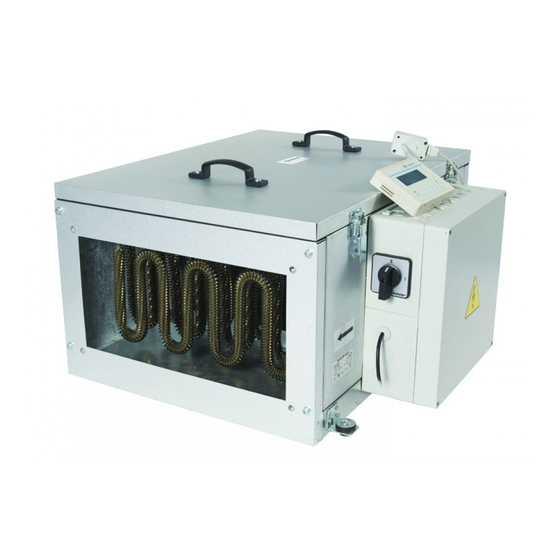
- Page 1 USER’S MANUAL MPA ... E Single-block air supply unit...
-
Page 2: Table Of Contents
CONTENTS Safety requirements ..................................3 Purpose ........................................ 5 Delivery set ......................................6 Designation key ....................................6 Technical data ....................................7 Design and operating principle ............................8 Mounting and set-up .................................. 9 Connection to power mains ..............................10 Unit control ....................................... 19 Storage and transportation regulations .......................... -
Page 3: Safety Requirements
SAFETY REQUIREMENTS • Please read the user’s manual carefully prior to installing and operating the unit. • All user’s manual requirements as well as the provisions of all the applicable local and national construction, electrical, and technical norms and standards must be observed when installing and operating the unit. - Page 4 • Do not touch the unit controls • Do not wash the unit with with wet hands. water. • Do not carry out the • Protect the electric parts of the installation and maintenance unit against ingress of water. operations with wet hands. •...
-
Page 5: Purpose
PURPOSE The unit is intended for filtering, supplying and heating purified intake air in private homes, offices, hotels, cafés, conference halls and other residential and public spaces. The unit is not intended for organizing ventilation in swimming pools, saunas, greenhouses, summer gardens and other spaces with high humidity. -
Page 6: Delivery Set
DELIVERY SET NAME NUMBER Air handling unit 1 pc. Control panel (for models with automation) 1 pc. Duct temperature sensor 1 pc. 1 pc. User’s manual Packing box 1 pc. DESIGNATION KEY XXXX Automation Number of supply voltage phases 1, 3 Heater type E –... -
Page 7: Technical Data
TECHNICAL DATA The unit is designed for application with the ambient temperature ranging from +1 °C to +40 °C and relative humidity up to 80 %. In order to prevent condensation on the internal walls of the unit, it is necessary that the surface temperature of the casing is 2-3 °C above the dew point temperature of the transported air. -
Page 8: Design And Operating Principle
MAIN TECHNICAL PARAMETERS Number Maximum Voltage Heater Heater of electric Sound pressure Number Fan current Air flow Weight ambient air Model [V] at 50 power current heating power level at 3 m of phases [min [kg] temperature [kW] elements distance [dBA] [°C] [pcs] MPA 800 Е1... -
Page 9: Mounting And Set-Up
MOUNTING AND SET-UP READ THE USER’S MANUAL PRIOR TO MOUNTING THE UNIT. The unit should be mounted so that the arrow on the cover coincides with air flow direction in the system in order to provide access for maintenance, servicing or replacement work. Enough space must be provided for the cover to open all the way. -
Page 10: Connection To Power Mains
CONNECTION TO POWER MAINS DISCONNECT THE UNIT FROM POWER MAINS PRIOR TO ANY OPERATIONS. THE UNIT MUST BE CONNECTED TO POWER MAINS BY A QUALIFIED ELECTRICIAN. THE RATED ELECTRICAL PARAMETERS OF THE UNIT ARE GIVEN ON THE MANUFACTURER’S LABEL. ANY TAMPERING WITH THE INTERNAL CONNECTIONS IS PROHIBITED AND WILL VOID THE WARRANTY. - Page 11 CONNECTION OF EXTERNAL DEVICES FOR MPA 800-2500 duct temperature sensor contacts X1:8, X1:9 signal leads from the automatic re-extinguishing system, contacts 1:17, 1:18 humidistat contacts X1:19, X1:20 control panel contacts 1:10, 1:11, 1:12, 1:13 CONTROL BOARD MPA-3200-3500 Control panel Duct temperature sensor min.
- Page 12 GENERAL VIEW AND WIRING DIAGRAMS OF CONTROL UNITS AND EXTERNAL DEVICES MPA 800 Control unit Opto-triac control unit « » blue broun « » black « » yellow-green Heater Di erential pressure sensor « » « » « » Duct sensor t° «...
- Page 13 MPA 1800, 2500 Opto-triac control unit « » blue Heater broun black « » « » yellow-green « » « » Di erential pressure sensor « » «RESET» « » Duct sensor t° « » Control panel Circuit « » «...
- Page 14 MPA 3200, 3500 www.ventilation-system.com...
- Page 15 MPA 3200, 3500 CONTROL UNIT Contacts for connecting a signal from an automatic Contacts for connecting a humidistat X5:3, X5:4 re extinguishing circuit X5:1, X5:2 Contacts for connecting an air damper X5:5, X5:6, X5:7 Damper actuator X5:5 (1) X5:6 (2) X5:7 (3) Additional options for external connections through the X5 terminal block are provided: •...
- Page 16 MPA-800 CONTROL UNIT www.ventilation-system.com...
- Page 17 MPA-1200-2500 CONTROL UNIT www.ventilation-system.com...
- Page 18 X1 TERMINAL BLOCK OF MPA-800 CONTROL UNIT X1 TERMINAL BLOCK OF MPA-1200-2500 CONTROL UNIT Terminal Terminal Circuit External connection Circuit External connection marking marking Power supply ~ 230 V Power supply ~ 400 V Power supply ~ 230 V Power supply ~ 400 V РЕ...
-
Page 19: Unit Control
UNIT CONTROL The unit is controlled using a remote control panel. FUNCTIONAL CAPABILITIES The system allows you to control the performance of the supply fan and has 3 speed levels: • 1 – minimal ventilation, used on weekends and holidays in non-residential premises or at night in residential premises •... -
Page 20: Manufacturer's Warranty
MANUFACTURER’S WARRANTY The product is in compliance with EU norms and standards on low voltage guidelines and electromagnetic compatibility. We hereby declare that the product complies with the provisions of Electromagnetic Compatibility (EMC) Directive 2014/30/EU of the European Parliament and of the Council, Low Voltage Directive (LVD) 2014/35/EU of the European Parliament and of the Council and CE-marking Council Directive 93/68/EEC. -
Page 21: Certificate Of Acceptance
CERTIFICATE OF ACCEPTANCE Unit Type Single-block air supply unit Model MPA__________________________________ Serial Number Manufacture Date Quality Inspector’s Stamp SELLER INFORMATION Seller Address Phone Number E-mail Purchase Date This is to certify acceptance of the complete unit delivery with the user’s manual. The warranty terms are acknowledged and accepted. - Page 22 www.ventilation-system.com...
- Page 23 www.ventilation-system.com...
- Page 24 V27EN-04...
Need help?
Do you have a question about the MPA E Series and is the answer not in the manual?
Questions and answers