Table of Contents
Advertisement
Quick Links
Advertisement
Chapters
Table of Contents

Subscribe to Our Youtube Channel
Summary of Contents for Clarke PRO-MIST DURA
- Page 1 INSTRUCTION MANUAL AND PARTS LIST PRO-MIST DURA® WITH SMARTFLOW II...
-
Page 2: Table Of Contents
TABLE OF CONTENTS PRO-MIST DURA® ULV WARRANTY INFORMATION WIRE CONNECTIONS PROMIST DURA INTRO LETTER BLOWER MOTOR ASSEMBLY 28 - 29 INSTALLATION 4 - 18 SPRAY HEAD ASSEMBLY 30 - 31 FORMULATION TANK ASSEMBLY 32 - 33 DESCRIPTION CONFIGURATION OPTIONS PLUMBING PATH/FLUID FLOW... - Page 3 TABLE OF CONTENTS PRO-MIST DURA® ULV SmartFlow II Manual 5. FILL TANK SIZE 6. TANK ALARM SET POINT SMARTFLOW II DESCRIPTION 61 - 62 7. MAX SNOOZE COUNT TOTAL COUNTERS OVERVIEW 8. MAINTENANCE ALERT TOTAL COUNTERS OPERATION 112 - 118...
-
Page 4: Warranty Information
WARRANTY PRO-MIST DURA® ULV Warranty Information Your Pro-Mist Dura is warranted to the original purchaser by Clarke against defects in workmanship or materials for a period of one (1) year from the date of purchase from Clarke. If any warranted... -
Page 5: Err
If you have questions about in a sealed bag or container. operating the sprayer, proper applications, or insecticides, call Clarke and ask for technical support. The spray head motor is a precision high speed device. Pay special attention to avoid any forceful Use only insecticides that are specifically registered... -
Page 6: Promist Dura Intro Letter
Electric power can be advantageous over gasoline engine power for aerial production and dispersal, especially when the rising cost of fuel is considered. Installation and removal of the Pro-Mist Dura from the vehicle on which it is carried requires minimum of effort because it has no heavy engine or compressor. In addition to its light weight, the Pro-Mist Dura ULV Sprayer features low energy requirements and low noise during operation. -
Page 7: Installation
Description The spray head produces a controlled droplet spectrum from liquid introduced inside the rapidly rotating porous The Pro-Mist Dura ULV Sprayer consists of four sleeve. Centrifugal force drives the liquid through the systems: pores to the outside surface of the sleeve where droplets are formed. -
Page 8: Configuration Options
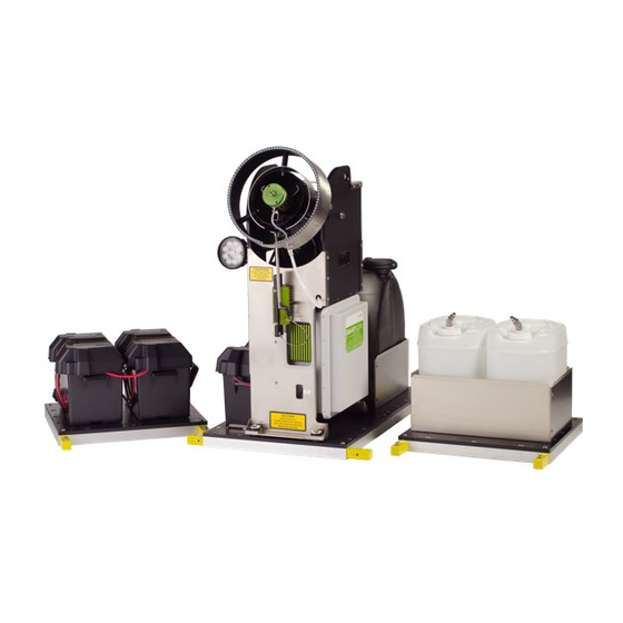
INSTALLATION PRO-MIST DURA® ULV Pro-Mist Dura Configuration Options The Pro-Mist Dura has been designed as a modular system and can be easily configured to meet your preference. Flexibility is made simple by connector shafts that let you mix and match separate pads housing the spray head, formulation tank/s and battery. -
Page 9: Uncrate And Remove From Skid
INSTALLATION PRO-MIST DURA® ULV Uncrate and Remove from Skid CAUTION: NO IMPACT TO SPRAY HEAD... -
Page 10: Mount To Vehicle
We recommend using 5/16 bolts with a flat washer. An option is to use pretreated wood beams (4 x 4) and bolt to bed of vehicle. The Pro-Mist Dura warranty is voided if the unit is damaged due to improper mounting. - Page 11 INSTALLATION PRO-MIST DURA® ULV Mount to Vehicle (Cont.)
-
Page 12: Supplying Power
Supplying Power The Pro-Mist Dura ULV Sprayer can be powered for a few hours running solely on its own fully charged 12 Volt Deep Cycle Battery, (e.g. a high quality ACM battery or deep cycle marine battery) mounted on the Blower Stand Base. -
Page 13: Mounting A Battery For
INSTALLATION PRO-MIST DURA® ULV Mounting a Battery on the Pro-Mist Dura for The Battery Box located on the Blower Stand Base is designed to hold up to a size “24M” marine battery. Self-Contained Operation A short power cord with plug is provided to connect You can expect a couple hours of operation from one this onboard battery to the blower stand power plug. - Page 14 Vehicle's Electrical System • Screw Driver For continuous operation, we recommend that the Pro-Mist Dura be connected directly to the vehicle's • Wrench Set up to 5/8” battery/charging system. An electrical Installation kit • Crimping Tool for Insulated Ring Lugs wire size is available from Clarke for this configuration.
-
Page 15: Connecting The Promist Dura To Your Vehicle'selectrical System
PRO-MIST DURA® ULV Connecting the Pro-Mist Dura to Your Vehicle's Electrical System (Cont.) Steps below depict connecting the ProMist Dura to Vehicle's electrical system, using the Clarke Electrical Installation Kit. Basically, this consists of hooking the vehicle's charging system to a power cable that will plug into the spray machine, as well as an on-board battery that will also plug into the machine and act as a buffer. - Page 16 INSTALLATION PRO-MIST DURA® ULV Connecting the Pro-Mist Dura to Your Vehicle's Electrical System (Cont.) Taking the long cable sections (now free Run both the black and red leads towards from the breaker) connect the plug end the front of the truck in the direction to the vehicle 12 volt input on the back of the vehicle’s battery and the mounted...
- Page 17 INSTALLATION PRO-MIST DURA® ULV Connecting the Pro-Mist Dura to Your Vehicle's Electrical System (Cont.) From the underside of the truck pull the cables through continuing towards the vehicle's battery and 50 amp breaker. Secure cables using cable ties and protect from...
- Page 18 INSTALLATION PRO-MIST DURA® ULV Connecting the Pro-Mist Dura to Your Vehicle's Electrical System (Cont.) Pulling the cables into the engine compartment to the mounted breaker, secure the ring terminal of the red cable to the breaker. The black cable will connect to the negative battery terminal in a future step of this instruction.
- Page 19 INSTALLATION PRO-MIST DURA® ULV Connecting the Pro-Mist Dura to Your Vehicle's Electrical System (Cont.) With these cables connected to the rear of the SMII control console determine the best mounting location within the cab. The included SMII mounting bracket can be used to secure the console within the cab. It is recommended to secure the console for safety purposes.
-
Page 20: Operation
OPERATION PRO-MIST DURA® ULV Before operating the sprayer: CAUTION: Do not spray when the vehicle is not 1. Check that all electrical cables and connections moving, or when backing up because this may are secure and clean. Be sure the battery is in good result in insecticide falling on the vehicle or its condition and the vehicle’s alternator charges at a... -
Page 21: Flushing
Pro-Mist Dura ULV Sprayer will clog. save the chemical (before a flush process dilutes it). Therefore, it is important that you spin dry the Hook up the tank line to the Park/Purge fitting. -
Page 22: Sprayer Maintenance
SPRAYER MAINTENANCE PRO-MIST DURA® ULV Sleeve Removal and Replacement The efficiency of the sprayer is largely a function of the cleanliness of the Hub and Sleeve assembly. It is ALWAYS a better choice to replace a sleeve that is suspected of being clogged rather than cleaning it. - Page 23 SPRAYER MAINTENANCE PRO-MIST DURA® ULV Sleeve Removal and Replacement (Cont.) NOTE: The base plate (as shown in picture 6) can be purchased separately: Part #332742 Hub can be secured to the blower Stand. Affix two small screw heads where indicated in picture 4A.
- Page 24 SPRAYER MAINTENANCE PRO-MIST DURA® ULV Sleeve Removal and Replacement (Cont.) The new Sleeve fits tightly onto the Using Both hands, press firmly straight Carefully secure the Retaining Hub; be sure to position the sleeve onto the Hub; be sure it is pressed below...
-
Page 25: Cleaning
SPRAYER MAINTENANCE PRO-MIST DURA® ULV Cleaning Pro-Flush will protect the system for extended periods and will leave a bit of lubricant in the pump and valve so Clean the external parts of a spraying machine after that they won’t seize during storage. -
Page 26: Spray Head & Audible
The Spray Head Audible Detection for Identifying Spray Head Imbalance The Pro-Mist Dura’s spray head uses a porous sleeve assembly, driven at 23-30,000 RPM, to produce The Spray Head or rotary atomizing device utilized by droplets from insecticide that has been introduced to the ProMist is a high-speed precision device that spins the inside of the assembly. -
Page 27: Parts Book And Components
PARTS BOOK AND COMPONENTS PRO-MIST DURA® ULV Table of Contents Parts Book and Components Tool List for Sprayer Maintenance page 25 Electrical Schematic page 26 Wire Connections page 27 page 28 - 29 Blower Motor Assembly page 30 - 31... -
Page 28: Tool List For Sprayer Maintenance
All assemblies can be replaced as well as a selection of spare parts. • 3/8" Drive Ratchet with 1/2" Deep Socket Call Clarke technical service, 800-859-2847 • 1/4" Drive Ratchet with 5/16" Regular Socket for guidance. • 1/4" Drive Ratchet with 3/8" Deep Socket Wrench •... -
Page 29: Electrical Schematic
ELECTRICAL SCHEMATIC PRO-MIST DURA® ULV Gray wire from EPD module White wire from blue pump White wire from the encoder... -
Page 30: Wire Connections
PARTS BOOK AND COMPONENTS PRO-MIST DURA® ULV Wiring Connections Motor Controller Connections Connection Panel Connections FEMALE CONNECTOR SMARTFLOW II 7-pin harness -12VDC common BLUE wire Wire #3 throttle signal 0-5 VOL EPD Breaker (downstream) ORANGE wire / EPD Replay wire from EPD... -
Page 31: Blower Motor Assembly
PARTS BOOK AND COMPONENTS PRO-MIST DURA® ULV Blower Motor Assembly Motor Blower Assembly Complete with Mount Fan Blade Machined Seal, Lip Clamp, 1 13/16 x 2 3/4, SS... - Page 32 PARTS BOOK AND COMPONENTS PRO-MIST DURA® ULV Blower Motor Assembly — Part Numbers DESCRIPTION PART NO. Blower Motor Assembly (complete with mount) 328444 Fan Blade, Machined 328428 Seal, Lip 328460 Clamp, 1 13/16 x 2 3/4, SS 329377...
-
Page 33: Spray Head Assembly
PARTS BOOK AND COMPONENTS PRO-MIST DURA® ULV Spray Head Assembly Spray Head Assembly Complete Disposable Porous Sleeve, Sold in 2-Pack (single shown) Nut, Flex top, 5/16-24, Thread Chased Retaining Ring Clamp, Disposable Porous Sleeve, 2-Pack 2.31 x 3.25 SS (Single shown above.) - Page 34 PARTS BOOK AND COMPONENTS PRO-MIST DURA® ULV Spray Head Assembly — Part Numbers DESCRIPTION PART NO. Spray Head Assembly (complete) 328832 Hub, GRN 340117 Disposable Porous Sleeve, Single 330233 Disposable Porous Sleeve 2 pack 331736 Retaining Ring, GRN 340125 Nut, Flex top, 5/16-24, Thread Chased...
-
Page 35: Formulation Tank Assembly
PARTS BOOK AND COMPONENTS PRO-MIST DURA® ULV Formulation Tank Assembly Assy Pickup Tube, 15 Gal. 15 Gal. Formulation Tank Assy Tank Cap Assy 15 Gal. Expansion Base Assy Includes Tank 5 Gal. Formulation Tank Assy Assy, Pickup Tube, 5 Gal. - Page 36 PARTS BOOK AND COMPONENTS PRO-MIST DURA® ULV Formulation Tank Assembly — Part Numbers DESCRIPTION PART NO. 15 Gallon Formulation Tank Assembly (Complete with Pickup Tube and Cap) 328303 Assembly Pickup Tube, 15 Gallon 328288 Tank Cap Assembly 319419 Assembly, Base, Exp 15 Gallon...
-
Page 37: Plumbing Path/Fluid Flow
PARTS BOOK AND COMPONENTS PRO-MIST DURA® ULV Plumbing Path/Fluid Flow Insecticide leaving formulation tank Enters filter/strainer Travels to the pump Through the damper From pump To spray head Following the tube on the quick connect on the spray head To and through the spray head NOTE: This is the bottom side of the spray head. -
Page 38: Plumbing Fluid Path Components
PARTS BOOK AND COMPONENTS PRO-MIST DURA® ULV Plumbing (Fluid Path Components) 15 Gal. Formulation Tank Assy 5 Gal. Formulation Tank Assy Coupler, tube, 3/8 Socket Strainer, Bowl T, PP, Clear (with fill screen) Filter Element for Strainer Seal, Strainer (chemical resistant for strainer) - Page 39 PARTS BOOK AND COMPONENTS PRO-MIST DURA® ULV Plumbing (Fluid Path Components, Cont.) LAB Pump Assembly (complete with sensor and fittings) Fitting, 90° 3/8" tube, 1/4" NPT Male Fitting, 90° Elbow 3/8" x 1/4" Damper Pulsation...
- Page 40 PARTS BOOK AND COMPONENTS PRO-MIST DURA® ULV Plumbing (Fluid Path Components, Cont.) Coupler, Tube, 3/8" (Plug) Coupling, QC Tube, Socket, mounted on Guard Tube, 3/8", PE (order by the foot) Coupling, QC, 1/4" Tube x 1/8 NPT Tube, 1/4", PE (order by the foot) (Quick-connect on spray head assembly.)
- Page 41 PARTS BOOK AND COMPONENTS PRO-MIST DURA® ULV Plumbing Path / Fluid Flow — Part Numbers DESCRIPTION PART NO. 15 Gallon Formulation Tank Assembly 328303 (Complete with Pickup Tube and Cap) 5 Gallon Formulation Tank Assembly 328296 (Single Tank assy, includes Pickup Tube) 329062 Coupler, Tube, 3/8", Socket (on inlet line)
-
Page 42: Pump/Electrical Cabinet
PARTS BOOK AND COMPONENTS PRO-MIST DURA® ULV Pump / Electrical Cabinet... - Page 43 PARTS BOOK AND COMPONENTS PRO-MIST DURA® ULV Pump / Electrical Cabinet (Cont.) Pump Box Assembly Complete With Pump and Electrical Cabinet Controller Motor Programmed Circuit Breaker, 15 Amp Circuit Breaker, 40 Amp Main ON/OFF Amp with Trip Relay,12V SPST,50A,4-TermBrkt *EPD Relay added in 2015 to ensure...
- Page 44 PARTS BOOK AND COMPONENTS PRO-MIST DURA® ULV Pump / Electrical Cabinet (Cont.) Relay, 12 VDC, 75A Converter, 12 VDC to 24 VDC...
- Page 45 PARTS BOOK AND COMPONENTS PRO-MIST DURA® ULV Pump / Electrical Cabinet (Cont.) LAB Pump Assembly Complete With Sensor and Fittings Harness 7 Pin Power/Flow (interior connection view) & Retainer, 7 Clip (small clip to secure harness to panel) Harness 10 Pin (interior connection view) &...
- Page 46 PARTS BOOK AND COMPONENTS PRO-MIST DURA® ULV Pump / Electrical Cabinet (Cont.) Interior Wiring Assy, Light/Relay Hookup (Work light Toggle with cabinet light and switch) Harness 7 Pin (Exterior Connection View) Harness 10 Pin (Exterior Connection View) Rear, Exterior Rear, Exterior...
- Page 47 PARTS BOOK AND COMPONENTS PRO-MIST DURA® ULV Pump / Electrical Cabinet (Cont.) Bracket and Sensor Assy EPD Module (Electronic Pump Driver) Fuse, 2A 3 AG Rear View of EPD Module...
- Page 48 PARTS BOOK AND COMPONENTS PRO-MIST DURA® ULV Pump/Electrical Cabinet — Part Numbers DESCRIPTION PART NO. Pump Box Assembly 328684 Complete with Pump & Electrical Cabinet 332304 Controller, Motor (Programmed) 321836 Circuit Breaker, 15 Amp Circuit Breaker, 40 Amp, Auto Reset...
-
Page 49: Main Assembly
PARTS BOOK AND COMPONENTS PRO-MIST DURA® ULV Main Assembly Assy, Blower Stand Assy, Base, includes 15 Gal. Tank Assy, Base, Dual, 5 Gal. (Includes Two Tanks) 15 Gal. Formulation Tank Assy (Complete, includes Pickup Tube and Cap) 5 Gal. Formulation... - Page 50 PARTS BOOK AND COMPONENTS PRO-MIST DURA® ULV Main Assembly (Cont.) Assy, Pump Box Flood Light, LED, 27W SmartFlow II includes Cables and Mounting Bracket Insert, Frame Joint Handle L, Adjust Pin...
- Page 51 PARTS BOOK AND COMPONENTS PRO-MIST DURA® ULV Main Assembly — Part Numbers DESCRIPTION PART NO. Assy, Blower Stand 328121 Assy, Base, includes 15 Gallon Tank 329682 Assy, Base, includes Dual 5 Gallon Tanks 332114 15 Gallon Formulation Tank Assembly 328303 Complete, includes Pickup Tube &...
-
Page 52: Blower Tube Assembly
PARTS BOOK AND COMPONENTS PRO-MIST DURA® ULV Blower Tube Assembly Assy, Blower Tube (without Spray Head Assy) Rear, Exterior Front, Exterior Side View Assy, Motor, Blower Ring, Extension, 8.5" (Complete Assy. with Bracket) Guard Ring, Extension, 13" Hose Clamp, 1 13/16 x 2 1/4, SS... - Page 53 PARTS BOOK AND COMPONENTS PRO-MIST DURA® ULV Blower Tube Assembly (Cont.) Mount, Shock, Blower Tube (6) Assy, Toggle Switch Terminal Strip, 4-Pos...
- Page 54 PARTS BOOK AND COMPONENTS PRO-MIST DURA® ULV Blower Tube Assembly (Cont.) LED Light Bar (Flexible Ring Light) Mount Spray Head Clamp, 2.31 x 3.25 SS (Spray Head Mount Clamp) Plate, Cover, Blower Tube, Rear...
- Page 55 PARTS BOOK AND COMPONENTS PRO-MIST DURA® ULV Blower Tube Assembly — Part Numbers DESCRIPTION PART NO. Assembly, Blower Tube (without Spray Head Assembly) 329707 Assembly, Motor Blower (Complete with Bracket) 328444 Hose Clamp, 1 13/16 x 2 3/4 SS (Blower Motor Mount Clamp) 329377 Ring, Extension, 8.5"...
-
Page 56: Available Accessories
PARTS BOOK AND COMPONENTS PRO-MIST DURA® ULV Available Accessories DESCRIPTION PART NO. DESCRIPTION PART NO. Assy, Expansion Base, includes 331538 Assy, Expansion Base, includes 329674 15 Gallon Tank (Not standard tank base.) two 5 Gallon Tanks (Not standard tank base.) DESCRIPTION PART NO. - Page 57 PARTS BOOK AND COMPONENTS PRO-MIST DURA® ULV Available Accessories (Cont.) DESCRIPTION PART NO. DESCRIPTION PART NO. Spanner Base Plate (work bench 332742 Assy, Spanner/Puller Tool 328973 mount to hold hub while using (necessary for removing hub spanner wrench) and changing sleeve) DESCRIPTION PART NO.
- Page 58 PARTS BOOK AND COMPONENTS PRO-MIST DURA® ULV Available Accessories (Cont.) DESCRIPTION PART NO. DESCRIPTION PART NO. Assy, Clarke Astro 5 GPS 325490 Fuse Holder, In-Line, AGU 333675 Speed Sensor/SmartFlow Fuse, AGU, 60 Amp, Fast 333691 Expansion Battery Base Cable Set...
-
Page 59: Spare Parts Kit (Expanded)
PARTS BOOK AND COMPONENTS PRO-MIST DURA® ULV Spare Parts Kit Components DESCRIPTION PART NO. Spare Parts Kit (Complete) 334219 Spare Parts Kit (Expanded) 10 Ft of part #319302 Tube 3/8" 319302 5 Ft of part #319295 Tube, 1/4" 319295 Coupling, QC Tube, Socket... -
Page 60: Parts List
PARTS LIST PRO-MIST DURA® ULV DESCRIPTION PART# PAGE # Blower Motor Assembly (complete with mount) 328444 Fan Blade, Machined 328428 Seal, Lip 328460 Clamp, 1 13/16 x 2 3/4, SS 329377 Spray Head Assembly (complete) 328832 Hub, GRN 340117 Disposable Porous Sleeve, Single... - Page 61 Assy, Install Kit SL (standard) 333815 Assy, Install Kit XL, (extended cab) 343228 Circuit Breaker, 50 Amp, Waterproof 333683 Assy, Clarke Astro 5 GPS speed sensor 325490 Fuse Holder, In-Line, AGU 333675 Fuse, AGU, 60 Amp, Fast 333691 Expansion Battery Base Cable Set...
- Page 62 INSTRUCTION MANUAL SMARTFLOW II...
-
Page 63: Smartflow Ii Manual
TABLE OF CONTENTS SMARTFLOW II SmartFlow II Manual 5. FILL TANK SIZE 6. TANK ALARM SET POINT SMARTFLOW II DESCRIPTION 61 - 62 7. MAX SNOOZE COUNT TOTAL COUNTERS OVERVIEW 8. MAINTENANCE ALERT TOTAL COUNTERS OPERATION 112 - 118 VOLUME STARTUP/SHUTDOWN AREA POWER UP MESSAGES... -
Page 64: Smartflow Ii Description
DESCRIPTION SMARTFLOW II SmartFlow II Installation, Operation and Maintenance Manual SMARTFLOW II CONSOLE Spray toggle for: Variable flow Continuous flow Power Toggle Data display window Application display window Reset button Light toggle Rate toggle for: Rate 1, 2 and/or 3 Spray head toggle Calibration button Maintenance Alert... - Page 65 DESCRIPTION SMARTFLOW II Installation, Operation and Maintenance Manual The SmartFlow II control provides programmable microcomputer control for Clarke spraying systems. The SmartFlow II control offers the following features: • The SmartFlow II control can operate alone, or for GPS-controlled Variable Rate...
- Page 66 TOTAL COUNTERS SMARTFLOW II Total Counters The SmartFlow II has five total counters: Total Counters Page 64 Volume Page 65 Area Page 65 Distance Page 66 Time Page 66 Hours Page 66...
-
Page 67: Total Counters Overview
TOTAL COUNTERS SMARTFLOW II Total Counters Overview The SmartFlow II accumulates the following totals to document spraying applications: COUNTER DESCRIPTION UNITS Volume The amount of liquid applied since the counter was Tenths of a gallon or tenths of a liter. last reset. -
Page 68: Area
TOTAL COUNTERS SMARTFLOW II Volume Counters Three Volume counters are provided. When in the Area is only accumulated while in the VARIABLE mode VOLUME position the selected counter is indicated (and not “Lo Speed” or “Hi Speed”) and all three by the Number icon (1, 2, 3) in the Data display and counters are active and will accumulate area (not just a different counter can be selected by using INC key. -
Page 69: Distance
TOTAL COUNTERS SMARTFLOW II Distance Time The DISTANCE position shows the distance traveled The TIME position displays the “spray time” since in 0.1 increments from 0 to 9,999.9 miles or km the counter was last reset. It displays from Distance is accumulated in Feet (or Meters). 0.1 to 9999.9 hours. -
Page 70: Smartflow Ii Control
CONTROL PANEL FUNCTIONS SMARTFLOW II Control Panel Functions This section describes the functions of the control panel for the SmartFlow II control. This section covers these control panel features: LCD Displays Page 68 Alarms Page 69 Warning LED Page 69 Rotary Dial Functions Pages 70 - 79 Toggle Switches... -
Page 71: Lcd Display
SMARTFLOW II LCD Displays The Clarke control box has two LCD displays, (Data display window and Application Rate display window) each of which is capable of displaying any combination of digits, decimal points, and icons as shown in the illustration below. -
Page 72: Alarms
CONTROL PANEL FUNCTIONS SMARTFLOW II Alarm On/Off Toggle Switch Warning LED An audible alarm (beeper) sounds when there is While in VARIABLE or CONTINUOUS mode, the an error. A rear mounted toggle switch (on the back Warning LED, and the Audible Alarm will turn on of the SmartFlow II console) is used to turn off (disable) (steady) whenever there is more than 10% error the audible alarm. -
Page 73: Rotary Dial Functions
CONTROL PANEL FUNCTIONS SMARTFLOW II Rotary Dial Functions The rotary switch is used to select the parameters to display and to set calibration values. The SmartFlow II has eight display functions and are selected by the rotary knob positions as described in this section. SMARTFLOW II CONSOLE Rotary Dial... - Page 74 CONTROL PANEL FUNCTIONS SMARTFLOW II Rotary Dial Functions (Cont.) Rotary Dial Position: DISTANCE Function: Distance Traveled The DISTANCE positions shows the distance traveled in 0.1 increments from 0 – 9,999.9 miles or kilometers and then increments from 10,000 – 99,999 miles or kilometers.* This is shown in the Data Display window.
- Page 75 CONTROL PANEL FUNCTIONS SMARTFLOW II Rotary Dial Functions (Cont.) 2. Rotary Dial Position: SPEED Function: Ground Speed When using GPS the distance is no longer measured The SPEED position shows ground speed in 0.1 directly, instead it is calculated by the GPS receiver. increments from 0.0 –...
- Page 76 CONTROL PANEL FUNCTIONS SMARTFLOW II Rotary Dial Functions (Cont.) 3. Rotary Dial Position: AREA 1, 2, 3 Function: Acres Sprayed Three Area counters are provided. When in the AREA position the selected counter is indicated by the NOTE: Once the display reaches 99,999 Number icon (1, 2, 3) shown in the Data display and a it will display OFL (Overflow) in the Data different counter can be selected by using the INC key.
- Page 77 CONTROL PANEL FUNCTIONS SMARTFLOW II Rotary Dial Functions (Cont.) 4. Rotary Dial Position: VOLUME/MINUTE Function: Ounces or Milliliters per Minute The VOLUME/MINUTE position shows a range from 0.001 – 16,777 oz/min or from 0.1 – 99,999 ml/min. A typical application is 1 oz/acre at a width of 300 ft. at 10 mph which generates a typical volume/minute of 6.060 oz/min or 179.2 ml/min.
- Page 78 CONTROL PANEL FUNCTIONS SMARTFLOW II Rotary Dial Functions (Cont.) 5. Rotary Dial Position: VOLUME (1)(2)(3) Function: Volume Pumped in Gallons or Liters Three Volume counters are provided. When in the VOLUME position the selected counter is indicated by the Number icon (1, 2, 3) in the Data display window and a different counter can be selected by using INC key.
- Page 79 CONTROL PANEL FUNCTIONS SMARTFLOW II Rotary Dial Functions (Cont.) 6. Rotary Dial Position: TANK Function: Amount of Liquid in the Tank The TANK position shows the amount of liquid remaining in the tank, to the nearest tenth of a gallon or liter. An alarm (see below) will be given when the Tank level equals or drops below the Set Point cal factor (default 2.0 gallons or 7.5 liters) while in VARIABLE, CONTINUOUS or OFF mode.
- Page 80 CONTROL PANEL FUNCTIONS SMARTFLOW II Rotary Dial Functions (Cont.) Rotary Dial Position: TIME Function: Time Spraying Since Counter Was Last Reset The TIME position displays the spray time since the counter was last reset. It displays from 0.1 – 9999.9 hours and then from 10,000 –...
- Page 81 CONTROL PANEL FUNCTIONS SMARTFLOW II Rotary Dial Functions (Cont.) 8. Rotary Dial Position: RATE Function: Displays Actual Rate in OZ/Acre or Milliliters/Hectare switching back and forth between decimal points. The RATE position displays in the “Data” display window and also will show the same value in the 2 or 3 decimal places 1.000 –...
- Page 82 CONTROL PANEL FUNCTIONS SMARTFLOW II Rotary Dial Functions (Cont.) NOTE: The Application Rate display window will always match the Rate displayed in the Data display window except for the following: • Displays Target Rate for 3 seconds when the Rate Toggle switch is changed and the “FILL” message does not alternate with it.
-
Page 83: Toggle Switches
CONTROL PANEL FUNCTIONS SMARTFLOW II Toggle Switches The SmartFlow II has six toggle switches: Power On/Off Switch The Power switch is a momentary, single-pole, single-throw (SPST) switch. NOTE: The Power switch is a momentary Single Pole, Single Throw (SPST) switch. In the up or ON positon the SPST switch contacts are open. - Page 84 CONTROL PANEL FUNCTIONS SMARTFLOW II Toggle Switches (Cont.) 2. Spray Head On/Off toggle switch turns the spray head on and off. SPRAYHEAD 3. Light On/Off toggle switch turns the work light on and off. LIGHT...
- Page 85 CONTROL PANEL FUNCTIONS SMARTFLOW II Toggle Switches (Cont.) MAINT. ALERT 4. Maintenance Alert TIME REMAINING The Maintenance Alert provides a countdown timer SNOOZE displayed in tenths of seconds which is used to monitor the condition of the “Disposable Sleeve” and works only when running in VARIABLE or CONTINUOUS mode with “RPM OK”...
- Page 86 CONTROL PANEL FUNCTIONS SMARTFLOW II Toggle Switches (Cont.) 5. Spray Toggle Switch The Spray toggle switch has three positions SPRAY VAR (Variable), CONT (Continuous), OFF (off mode, not Power Off). CONT Spray Toggle Switch Positions CALIBRATION FACTOR DESCRIPTION VAR Position Variable Mode The SmartFlow control varies the pump speed to automatically maintain the selected application rate based on flow and speed.
- Page 87 CONTROL PANEL FUNCTIONS SMARTFLOW II Toggle Switches (Cont.) The “Continuous” speed Calibration value can be set from 2.0 – 45.0 mph (or kph) and the same speed is used for all 3 Rates. If the “speed” position is selected CONT: on the rotary switch, it will flash the “Continuous The CONTINUOUS mode can be used to spray while Speed”...
- Page 88 CONTROL PANEL FUNCTIONS SMARTFLOW II Toggle Switches (Cont.) 6. Rate Toggle Switch This toggle switch is used to select from 1 to 3 pre-programmed application rates for VARIABLE or RATE CONTINUOUS spray rate control. A number icon 1, 2, 3 will turn on in the Application Rate display window RATE 1 to reflect which rate is selected.
-
Page 89: Push Buttons
CONTROL PANEL FUNCTIONS SMARTFLOW II Push Buttons The SmartFlow II has four push buttons. When the RESET button is pressed it will immediately display “CLEAr” in the Data display window as a Their functions are described below: warning that it is about to clear counters. If the RESET 1. - Page 90 CONTROL PANEL FUNCTIONS SMARTFLOW II Push Buttons 2. INC (+) and 3. DEC (-) The INC/DEC buttons are used to enter or adjust values in the display. If in Volume or Area mode the INC/DEC buttons will select 1 of 3 counters. If in the Tank mode then the INC or DEC buttons are used to change the Tank level.
-
Page 91: Calibration
CALIBRATION SMARTFLOW II CALIBRATION 89 - 102 CALIBRATION FACTORS OVERVIEW HOW TO ENTER THE 90 - 91 CALIBRATE MODE ALARM SETTING SPEED CAL CONT. SPEED TEST SPEED TARGET RATE 95 - 96 MIN SPEED MAX SPEED FLOW CAL HOW TO CALIBRATE RELOADING CALIBRATION 101 - 102 DEFAULTS... -
Page 92: Calibration Overview
CALIBRATION SMARTFLOW II Calibration Factors Overview The SmartFlow II control has 8 calibration factors: CALIBRATION FACTOR ROTARY SWITCH POSITION DESCRIPTION Alarm Setting AREA (1) (2) (3) Sets the delay time for triggering the audible alarm. Speed Cal DISTANCE Specifies the distance the vehicle travels between speed sensor pulses. - Page 93 CALIBRATION SMARTFLOW II How to Enter Calibration Mode Two methods can be used to enter the Calibrate mode. NOTE: The audible alarm remains off Only allows user to view the Cal factors. To enter while in either Cal mode except when “View”...
- Page 94 CALIBRATION SMARTFLOW II How to Enter Calibration Mode (Cont.) 2. Allows user to view and change the cal factors. To enter “View and Change” Calibration Mode: • Toggle the Spray Switch to OFF. SPRAY • Turn Rotary switch to Target Rate” position. Press and hold both the CAL and INC button CONT for 1 second.
- Page 95 CALIBRATION SMARTFLOW II Calibration Factors 1. Alarm Setting The ALARM SETTING calibration factor is used to set *NOTE: This delay setting only affects the delay time for triggering the audible alarm*. the audible alarm, it does not affect any This delay can be changed from 0 – 6 seconds. visual alarm (warning LED).
- Page 96 This Speed is used for all Application Rates when in fall from pulse to pulse). the CONTINUOUS mode. When using the Clarke Astro 5 GPS speed sensor, 1. To set the CONT SPEED factor: Place the SmartFlow the user must set Speed Cal to zero (no calibration is II in Calibration mode by placing the rotary dial to required).
-
Page 97: Calibration Factors
CALIBRATION SMARTFLOW II Calibration Factors 4. Test Speed TEST SPEED is not a true “calibrate factor” but rather To exit Test Speed: a method of testing the sprayer. Typically it is used to Hold the CAL button for 1 second (or turn the confirm that Auto Control can be maintained across a SmartFlow II off) and the CAL icon will stop flashing, range of expected ground speeds. -
Page 98: Target Rate
CALIBRATION SMARTFLOW II Calibration Factors 5. Target Rate TARGET RATE displays the Target Application rate English Units: for VARIABLE and CONTINUOUS mode (automatic When slowly increasing from 0 to maximum, the control). Up to three different Target Rates can be decimal point will automatically shift at the following programmed in oz/acre or from mLiter/Hectare. - Page 99 CALIBRATION SMARTFLOW II Calibration Factors 5. Target Rate (Cont.) Metric Units: When slowly increasing from 0 – maximum the decimal will shift at the following values: DECIMAL PLACES RANGE 0.1 – 99.9 None 100 – 99,999 (then goes to OFL) TARGET RATE When slowly decreasing from maximum to 0 the deci-...
-
Page 100: Min Speed
CALIBRATION SMARTFLOW II Calibration Factors (Cont.) 6. Min Speed MIN SPEED displays the “Minimum Speed” which can be adjusted from “off” to 0.1 to 45.0 mph or kph. If used, the user must ensure that Min Speed is less than Max Speed (if used) or else the sprayer will never turn Min Speed is used to stop the sprayer (and Distance, SPEED... -
Page 101: Max Speed
CALIBRATION SMARTFLOW II Calibration Factors (Cont.) 7. Max Speed MAX SPEED displays the “Maximum Speed” which can be adjusted from “Off” to 0.1 to 45.0 mph or kph. If used, the user must ensure that MAX SPEED is greater than Min Speed (if used) or else the sprayer will never SEED turn on. - Page 102 CALIBRATION SMARTFLOW II Calibration Factors 8. Flow Cal In the Flow Cal position the current Flowmeter Calibrate factor value will be displayed. This specifies the FLOW number of flow sensor pulses per gallon applied. This enables the SmartFlow II control to accurately measure total flow, flow per minute and application rate.
-
Page 103: How To Calibrate
CALIBRATION SMARTFLOW II To Calibrate: 13. Save Rotate the rotary dial to TARGET RATE, press Fill your formulation tank. and hold the CAL button for 3 seconds to save the 2. Power move the SmartFlow II POWER toggle change and exit Calibration mode. switch to “ON”. -
Page 104: Reloading Calibration Defaults
CALIBRATION SMARTFLOW II Reloading Calibration Defaults Default Calibrate factors are loaded, and all Counters are cleared, if the CAL and DEC buttons are held while turning the SmartFlow II on. If the rotary switch is in the position, it will select the Metric Units and load Metric defaults. Any other rotary position will select English units and load English defaults. - Page 105 CALIBRATION SMARTFLOW II Reloading Calibration Defaults (Cont.) To confirm that defaults were actually loaded, the SmartFlow II will display LOAd for at least 1.5 seconds or as long as the CAL or DEC buttons are held, up to 3 seconds. If the CAL and DEC buttons are held for 3 seconds, the display will change to StorE and the defaults will be saved to EEPROM.
-
Page 106: Special Calibration Modes
SPECIAL CALIBRATION MODES SMARTFLOW II Special Calibration Modes This section covers these special calibration modes and procedures: Special Calibration Modes pages 104 - 105 1. Units page 106 2. Vehicle ID page 106 3. Width page 106 4. Control Speed page 106 page 107 5. - Page 107 SPECIAL CALIBRATION MODES SMARTFLOW II Special Calibration Modes NOTE: Some positions on the rotary dial will When in Special Calibrate mode various words will be direct you to a second feature when the CAL displayed in the Application Rate display window to help button is pressed quickly (less than 1 second).
- Page 108 SPECIAL CALIBRATION MODES SMARTFLOW II Special Calibration Modes To access the new Special Calibration functions: • Turn Dial to RATE • Press and hold the CAL button and RESET buttons together, AND turn on the MAIN POWER switch on the machine simultaneously. This may require another person to help if the console is mounted in the vehicle.
- Page 109 SPECIAL CALIBRATION MODES SMARTFLOW II Special Calibration Modes (Cont.) 3. Width 1. Units Selecting Time position displays UU idE in the Application Rate display and allows user to change Selecting Area position displays Unit in the Application the Width from 0.1 to 6,553.5 feet or 0.01 to Rate display and allows the user to change the Units.
-
Page 110: Fill Tank Size
SPECIAL CALIBRATION MODES SMARTFLOW II Special Calibration Modes (Cont.) 5. Fill Tank Size Selecting Volume position displays "SIZE" in the Application Rate display allows the user to enter a FILL TANK SIZE which can be toggled to OFF for 0.1 to 6,553.5 Gallons or Liters. PPR (Pulses Per Revolution) This feature is under the "Volume 1,2,3"... -
Page 111: Tank Alarm Set Point
SPECIAL CALIBRATION MODES SMARTFLOW II Special Calibration Modes (Cont.) 6. Tank Alarm Set Point Selecting the Volume/Minute position displays SEEPE in the Application Rate display and allows the user to change the TANK ALARM SETPOINT which can be toggled to OFF or set from 0.1 to 6,553.5 Gallons or Liters. -
Page 112: Max Snooze Count
SPECIAL CALIBRATION MODES SMARTFLOW II Special Calibration Modes (Cont.) been activated a “−" sign is displayed before the time remaining to indicate that the Sleeve is running 7. Max Snooze Count on “borrowed time”. SH Lo, Spray Head RPM Low Limit This feature is Selecting Tank in special calibrate mode displays found under the "Tank"... -
Page 113: Maintenance Alert
Target speed. Until the motor warms up and the Target Speed is reached the display will read 5h The SmartFlow II controller for the Pro-Mist Dura comes Lo in the Applications Rate Window. with a new feature that helps you keep track of the... -
Page 114: Operation
OPERATION SMARTFLOW II Operation This section covers these operating procedures: Startup/Shutdown Page 112 Power Up Messages Pages 113 - 114 Selecting the Application Rate Page 115 Page 116 Clearing Counters Page 117 Adjusting Tank Volume Resetting After a Maintenance Alert Shut Down Page 118... - Page 115 OPERATION SMARTFLOW II Startup/Shutdown Step by Step SmartFlow II Operation Make sure SPRAY button is in OFF position on SPRAY the SmartFlow II console. Place RATE switch in position RATE 1, RATE 2 CONT or RATE 3. (No need to turn on the power switch on the console as the power switch automatically defaults to the on position.) You must turn on main ON/OFF switch, located on the rear of the actual machine.
-
Page 116: Power Up Messages
OPERATION SMARTFLOW II Power Up Messages When the SmartFlow II is turned on it will give a very short beep and flash the Warning LED to ensure they are working. It will then display the number of hours it has operated in 0.1 hour increments up to a maximum of 9999.9 hours (then it will display OFL). - Page 117 OPERATION SMARTFLOW II Power Up Messages (Cont.) Bad Cal At power the SmartFlow II performs a verification of its stored memory (EEPROM). If it detects a problem it will display “bAd CAL” and wait for the user to press the CAL button. bAd CAL It will then enter “view only”...
-
Page 118: Selecting The Application Rate
OPERATION SMARTFLOW II Selecting the Application Rate To select a preset application rate, flip the toggle switch to the desired rate (RATE 1, RATE 2, or RATE 3) and this will be displayed in the APPLICATION RATE window. RATE RATE 1 RATE 2 RATE 3 SPRAY... -
Page 119: Clearing Counters
OPERATION SMARTFLOW II Clearing Counters When Area and Volume 1 (only) are selected the RESET key will clear four counters (Area 1, Volume 1, Distance and Time) at the same time. When in the OFF mode, and in the Distance, Area, Volume or Time rotary position pressing the RESET key for 1 second will clear Time, Distance, Area 1 and Volume 1 (four counters). -
Page 120: Adjusting Tank Volume
OPERATION SMARTFLOW II Adjusting Tank Volume You should adjust the tank volume to match the actual volume of pesticide liquid in your tank each time you fill the tank. The TANK position (using rotary switch) shows the amount of liquid remaining in the tank, to the nearest tenth of a gallon or liter. -
Page 121: Resetting After Amaintenance Alert Shut Down
OPERATION SMARTFLOW II Resetting After a Maintenance Alert Shut Down With the SPRAY toggle switch in OFF, holding the TIME REMAINING toggle and then also pressing the RESET button for 1 second will reset the Maintenance Alert timer to its preset value. Activating and Customizing the Maintenance Alert Feature SPRAY... -
Page 122: Troubleshooting
TROUBLESHOOTING SMARTFLOW II Troubleshooting This section covers these warning indicators: page 120 Alarm Indicators Error Codes pages 121 - 125 Err 1 pages 121 - 124 Spray head speed (rpm) not within limits; SH NO, SH Lo, SH Hi & Audible Detection For Spray Head Imbalance Err 2 page 124... - Page 123 TROUBLESHOOTING SMARTFLOW II Always inspect the power connection to the vehicle and the onboard battery as well as the SmartFlow II cables for any damage or poor connections. This should always be the first check before any additional troubleshooting. Alarm Indicators The following indicators can be used as reminders to the operator to inspect the Sleeve condition: Sleeve Condition...
- Page 124 TROUBLESHOOTING SMARTFLOW II Error Codes — Err 1 Error Code 1 NOTE: Low Limit is set at 23,000 RPM. Spray head speed (rpm) not within limits Low Limit will stop chemical pump until speed above 23,500 RPM is reached. Condition: Re-adjust to 28,000 RPM with chemical off.
- Page 125 TROUBLESHOOTING SMARTFLOW II Error Codes — Err 1 (Cont.) NOTE: If the Spray Head is not running and increasing the rpm setting has no effect see below information on fault codes to help identify the issue. If no Green LED or blinking red LED codes (in the pump box) are displayed, go to “Check 2”...
- Page 126 For an over temp warning, allow unit to cool. Upon cooling, if machine functions, document conditions resulting in fault, e.g. Speed, Ambient Temperature, Dispensing Rate, DC Amps and contact Clarke technical service for assistance. For a fail to start no rpm error, rotate the spray head carefully by hand;...
- Page 127 If 5 volts present, check voltage at red wire and rotate motor and inspect voltage. If it fluctuates, sensor is likely good. If not, replace sensor. Check 2 Disassemble pump from motor and replace frozen component. Contact Clarke technical service for assistance.
- Page 128 If 5 volts present, check voltage at red wire and rotate motor and inspect voltage. If it fluctuates, sensor is likely good. If not, replace sensor. Check 2 Disassemble pump from motor and replace frozen component. Contact Clarke technical service for assistance.
- Page 129 TROUBLESHOOTING SMARTFLOW II Messages and Warnings The Consoles will display the following messages (in alphabetical order) for the conditions indicated: DISPLAY CONDITION bAd CAL if EEPROM Check Sum equals zero or fails at power up. Shown in App Rate display to help indicate Cal mode is selected.
- Page 130 TROUBLESHOOTING SMARTFLOW II Messages and Warnings (Cont.) DISPLAY CONDITION SEEPE In App Rate display to indicate Special Cal Tank ‘Set Point’ is selected. In App Rate display to indicate SPECIAL CAL mode is selected. SPEC In App Rate display to indicate Special Cal Tank ‘Size’ is selected. S1 2E Has stored Default Cal Factors to non-volatile memory.
- Page 131 TROUBLESHOOTING SMARTFLOW II Messages/Warnings: No Light Operation Check 3 Condition Disconnect 7 pin wire cable from pump box; measure Light switch engaged on console, Work Light for voltage between the two large terminals of the 7 pin not activated. connector (thick Blue and Orange wires). Check 1 Repair Verify that the light breaker circuit breaker is not...
-
Page 132: Warning Led & Audible Alarm
TROUBLESHOOTING SMARTFLOW II Messages/Warnings: Messages/Warnings: Warning LED & Audible Alarm Low Voltage Detection While in VARIABLE or CONTINUOUS mode, the When the supply voltage drops below minimum the Warning LED, and the Audible Alarm will turn on required operating range, the Data display will display (steady) whenever there is more than 10% error in the “Lo P”... - Page 133 ™ GLOBAL HEADQUARTERS 675 Sidwell Court, St.Charles, IL 60174 USA Phone: 1 (630) 894-2000 Fax: 1 (630) 443-3070 www.clarke.com © Clarke. SmartFlow II and ProMist are trademarks of Clarke. ProMist is a registered U.S. trademark of Clarke. 2020 032020...
Need help?
Do you have a question about the PRO-MIST DURA and is the answer not in the manual?
Questions and answers