Table of Contents
Advertisement
Quick Links
Advertisement
Table of Contents

Summary of Contents for Sedanamedical AMG-06
- Page 1 Multigas Analyzer AMG-06 User manual ТESM.943129.002 UM Edition 3, 05.04.2020...
-
Page 3: Table Of Contents
CONTENT DEVICE DESCRIPTION .................... 5 INTRODUCTION ....................5 1.1.1 Intended Use and Scope ..................9 1.1.2 General Guidance ....................9 1.1.3 Revision History ....................10 1.1.4 Safety Precautions ....................11 1.1.5 Electromagnetic compatibility ................12 1.1.6 Operation principle ....................12 1.1.7 Basic Technical Characteristic ................12 COMPONENTS OF THE DEVICE AND MARKING ..........16 1.2.1 Information Display ....................16 1.2.2 Water trap ......................16... - Page 4 INTERNAL BATTERY ..................57 3.5.1 Battery Cycling ....................59 MAINTENANCE ....................... 60 TROUBLESHOOTING ..................... 61 DELIVERY SET ....................... 62 STORAGE ....................... 63 TRANSPORTATION ....................64 DISPOSAL ....................... 65 WARRANTY ......................66 CERTIFICATE OF ACCEPTANCE ............... 69 COMMISSION DATE MARK ................70 MAINTENANCE AND REPAIR DATA..............
-
Page 5: Device Description
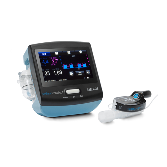
DEVICE DESCRIPTION 1 DEVICE DESCRIPTION INTRODUCTION The present user manual applies to the Multigas Analyzer AMG-06 (hereinafter – the device). The manual is intended for trained medical personnel using the device. Appearance of the device is presented in Figure 1.1. - Page 6 DEVICE DESCRIPTION • RS232 connector (marked as “RS232”). Device right side panel is shown in Figure 1.2. 1 - Outlet port; 2 - power adapter connector; 3 - RS232 connector. Figure 1.2 – Device right side panel A slot for the water trap is placed at the left-side panel of the device (Figure 1.3, position 1).
- Page 7 DEVICE DESCRIPTION 1 - slot for water trap; fastener with swivel unit; lock button of the fastener swivel unit; 4 - lock button of water trap. Figure 1.3 – The left panel of the device The fastener system enables the device to be fixed on most surfaces and bedside ob- jects.
- Page 8 DEVICE DESCRIPTION 1 - fastener handle; 2 - fastener body; 3 - fastener pin; 4 - fastener pad; 5 - fastener grip. Figure 1.4 – The rear panel of the device а) on horizontal arm b) on inclined arm Figure 1.5 – Examples of the device fixation The first item is motionlessly located on the fastener body, the second one is affixed to the screw-threaded pin, that enable the device to be easily fixed with handle on objects of different shapes and diameters.
-
Page 9: Intended Use And Scope
DEVICE DESCRIPTION 1.1.1 Intended Use and Scope The device is intended for continuous non-invasive monitoring of СО , isoflurane (ISO), sevoflurane (SEV), desflurane (DES) concentration in inspired (FiCO , FiDES, FiISO, FiSEV) and expired (EtCO , EtDES, EtISO, EtSEV) gas without automatic identification of anaesthetic, and also for determining patient’s respiration rate (RSP) and apnea, MAC index, and measur- ing atmospheric pressure under the conditions of operation rooms and wards when providing anaesthetic support. -
Page 10: Revision History
DEVICE DESCRIPTION • the device is used in accordance with the User manual; • after-sales service and repairs are performed by persons with required qualification and instruments and authorized by Triton Electronic Systems Ltd. Contacts: Manufacturer Authorized Representative in EU Triton Electronic Systems Ltd. -
Page 11: Safety Precautions
DEVICE DESCRIPTION 1.1.4 Safety Precautions The device is designed only for visual monitoring and automatic registra- tion of patient’s physiological parameters and does not relieve medical personnel of the responsibility of continuous physical supervision over patient. The device is intended for use under the direct supervision of medical per- sonnel. -
Page 12: Electromagnetic Compatibility
During operation it is necessary to use the power adapter supplied with the device. 1.1.6 Operation principle The Multigas Analizer AMG-06 is a side-stream gas analyzer, where the portion of gas from the patient’s breathing circuit is transferred to the device for analysis through the sampling tube. - Page 13 DEVICE DESCRIPTION Table 1 Operating parameters Parameter Value (description) Main parameters , and anaesthetic agents alternately Measured gases SEV or DES or ISO. FiCO , FiDES, FiISO, FiSEV, EtCO , EtDES, EtISO, EtSEV, RSP Measurement parameters Inspired and expired concentration of CO and anaes- thetic agent, respiration rate ISO accuracy within 45 s (warming-up time)
- Page 14 DEVICE DESCRIPTION Parameter Value (description) Sampling gas flowrate range 50-250 ml/min Accuracy of sampling gas ±10 ml/min (or ±10% whichever is greater) flowrate Response time (sampling tube 200 cm, sampling gas flowrate 2.5 s, depends on monitoring rate 250 ml/min) 0 –...
- Page 15 DEVICE DESCRIPTION Parameter Value (description) Transportation conditions Ambient air temperature from -50 to 50 °C not over 80 % (at the air temperature 25 ºС) Relative humidity Standards • Concerning safety, the device complies with IEC 60601-1, ISO 80601-2-55. • Concerning electromagnetic compatibility (EMC), the device meets the requirements of IEC 60601-1-2.
-
Page 16: Components Of The Device And Marking
DEVICE DESCRIPTION COMPONENTS OF THE DEVICE AND MARKING The device consists of information display with TFT-touch screen, button with led indica- tors, water trap, sampling tube, exhaust gas tube, power adapter. After transportation or storage at below-zero temperature it is necessary to hold the device at room temperature in the package for at least 12 hours before switching on. -
Page 17: Sampling Tube
DEVICE DESCRIPTION Maximum emptying interval during normal use (operating temperature 23°C, patient res- piration gas 37° and 100% RH) is 17 hours at sample flowrate 200 ml/min or 26 hours at flowrates below120 ml/min. Replace the water trap every month or more often if necessary. Handle the contents of the water trap as it would be handled any bodily liquids. -
Page 18: Symbols
DEVICE DESCRIPTION 1 – body of power adapter; 2 – power cable; 3 – connector for electronic unit. Figure 1.6 – Power adapter 1.2.6 Symbols Symbols on device housing Refer to the accompanying documents! ON/OFF button Power Power led indicator of ON/OFF button Battery Battery led indicator of ON/OFF button Class II medical electrical equipment while powered from external alternative current... -
Page 19: Interface Description
DEVICE DESCRIPTION Symbols in interface Sound alarm pause button “Monitoring” tab “Trend/Alarm log” tab “Settings (1 and 2)” tab “Advanced settings” tab Battery charging process The battery charge level is about 100 % The battery charge level is about 50 % The residual battery charge is less than 20 % Left scroll button of alarms and events field Right scroll button of alarms and events field... - Page 20 DEVICE DESCRIPTION а) Monitoring b) Trends c) Alarm log d) Settings1 i) Settings 2 f) Advanced settings g) Patient information h) Wi-Fi settings Figure 1.7 – Device interface...
-
Page 21: Monitoring" Screen
DEVICE DESCRIPTION “Monitoring” is the default screen when the device is powered on. Switching between the screens is performed by pressing the mode switching buttons (herein- after - “tabs”) at the top of the device screen: Monitoring Trends/Alarm log Settings (1 and 2) Advanced settings Figure 1.8 –... - Page 22 DEVICE DESCRIPTION 1 - Tabs panel; 2 - FiCO window (description of parameter windows at Figure 1.11); 3 - EtCO window; 4 - EtAx window (EtAx cases: EtIso. EtSev, EtDes); 5 - FiAx window (FiAx cases: FiIso. FiSev, FiDes); 6 - RSP window; 7 - Status bar;...
- Page 23 DEVICE DESCRIPTION Figure 1.10 – “Monitoring” screen (default screen without FiCO , FiAx) 1 - parameter title; 2 - high limit; 3 - parameter value; 4 - low limit; 5 - measurement unit; 6 - parameter window background. Figure 1.11 – Parameter window Color of highlighted parameter on the yellow background: •...
- Page 24 DEVICE DESCRIPTION • normal limit – blue; • alarm limit – red; • measurement unit – blue. Color of highlighted parameter on the red background (only apnea, when respiration rate is zero during set apnea time in the “Settings 1 screen”): •...
- Page 25 DEVICE DESCRIPTION Figure 1.12 – Graph menu, Amplitude Graph window enables setting a sweep speed (mm/s) after pressing the graph window: 8, 7, 6, 5, 4, 3. Sweep speed setting in graph menu is shown in Figure 1.13. Figure 1.13 – Graph menu, Sweep speed Sweep speed also may be set in the “Setting 2”...
-
Page 26: Trends" Screen
DEVICE DESCRIPTION button for selection (selection with blue color) and change limit value by slider moving or press “+” or “-” buttons. 1 - title of limits menu; 2 - scroll left button; 3 - limit button; 4 - “-” button for decrement value; 5 - slider;... - Page 27 DEVICE DESCRIPTION monitoring over time. The data recorded by the device on monitored parameters (FiCO EtCO , FiAx, EtAx) are automatically stored in its non-volatile memory. A trend starts at the moment when the device is powered on, and finishes at the moment of switching off. Trends are provided with time labels.
- Page 28 DEVICE DESCRIPTION Figure 1.16. Trends graph enables to set an amplitude of CO after pressing the trends graph window: • Amplitude 1 – CO max value 8%, 60 mmHg (according measurement unit). • Amplitude 2 – CO max value 16%, 120 mmHg (according measurement unit). Figure 1.16 –...
- Page 29 DEVICE DESCRIPTION Scroll area start time marker; Scroll left button “Summary” button; Frame size button; Power on marker; High alarm marker; Event alarm marker; Medium alarm marker; Frame position marker (center frame time); 10 - Scroll right marker; 11 - Scroll area end time marker; 12 - Length scroll area button;...
- Page 30 DEVICE DESCRIPTION Note: scroll area time start and end markers, frame position marker show real date and time which were set in the device when alarm happens. The “Alarm log” screen displays the real time of alarms and events occurrence. Real time does not affect the duration of alarms/events displayed in the alarm table.
- Page 31 DEVICE DESCRIPTION • Physical – contains only physical alarms and power on markers. • System – contains technical alarms, events and power on markers. Figure 1.19 – Navigation panel, Scroll area length setting More detailed information about alarms and events see at section 2.5 “Alarm system”. Navigation panel with frame view contains alarm pointer that can be moved by pressing the channels area.
-
Page 32: Alarm Log" Screen
DEVICE DESCRIPTION Frame start time marker; “Channels” button; Title of physical channel; Title of system channel; High alarm marker; Event alarm marker; Power on marker; Alarm pointer; Medium alarm marker; 10 - Frame end time marker; 11 - Title frame view; 12 - Channels area;... - Page 33 DEVICE DESCRIPTION • high priority alarm - red; • medium priority alarm - yellow; • low priority alarm – blue; • events – gray; • power on events – green; Selected row; alarm table; navigation panel; forward scroll button; alarm filter; back scroll button;...
- Page 34 DEVICE DESCRIPTION Note: the alarm table is not a static list of alarms or events. A user should consider the logic of forming the alarm table and examples. New table generation starts when the alarm pointer changes its position or it is initial alarm table formation.
-
Page 35: Settings 1" And "Settings 2" Screens
DEVICE DESCRIPTION Figure 1.23 – Alarm table generation, example 2 It is necessary to clear alarms and events log as well as patient infor- mation after each use and before commissioning, maintenance, and ship- ment for repair to the manufacturer. Press button “Clear Logs”... - Page 36 DEVICE DESCRIPTION 1 - Parameter value; 2 - selected parameter; 3 - unselected parameter; 4 - “-” button for decrement value 5 - slider; 6 - “+” button for decrement value; Figure 1.24 – “Settings 1” screen Unit parameter list: %, mmHg, kPa. FiCO , EtCO , FiAx, EtAx parameters will be recal- culated when the parameter «Unit»...
- Page 37 DEVICE DESCRIPTION Checkbox «Use Desflurane» states: • checked – enable DES in unit list in the «Settings 1» screen; • unchecked – disable DES in unit list in the «Settings 1» screen; 1 - Calibration button; 2 - day; 3 - month; 4 - year;...
- Page 38 DEVICE DESCRIPTION • checked – current graph CO and anaesthetic values will be displayed in the «Monitoring» screen; • unchecked – current graph CO and anaesthetic values will be hidden in the «Monitoring» screen; Checkbox default state when the device is powered on: •...
-
Page 39: Advanced Settings" Screen
DEVICE DESCRIPTION 1.3.5 “Advanced settings” screen The “Advanced settings” screen is intended for advanced setting the device, enter patient information and view the device info. To access the corresponding information (Figure 1.27) click on the “Advanced settings” tab. In the middle of the screen there is an information block “Information”, which contains the patient's surname name in the patient field, the status of the device connection via Wi-Fi to an external medical information system (hereinafter - MIS) is displayed in the “MIS state”... - Page 40 DEVICE DESCRIPTION Figure 1.27 – “Advanced Settings” screen Press “Clear logs” to display the pop-up menu “Clear logs” with two choices: • “No” - cancel clearing logs and patient information; • “Yes” - clearing the trend and alarm logs and patient information. Press the “Factory reset”...
-
Page 41: Wi-Fi Settings" Screen
DEVICE DESCRIPTION 1.3.6 “Wi-Fi settings” screen Press on the “Wi-Fi settings” button in the “Advanced settings” screen to go to the win- dow to review or modify the Wi-Fi settings. The “Wi-Fi settings” screen contains Wi-Fi param- eters and virtual keyboard as shown in Figure 1.28. Requirements for the Wi-Fi access point are given in Appendix B. -
Page 42: Patient Information" Screen
DEVICE DESCRIPTION • “Wi-Fi disconnected” - no connection to a Wi-Fi network; • “Wi-Fi connected” - there is a connection to a Wi-Fi network; • “Setting IP” - setting the IP address of the device received from the access point's DNS server;... - Page 43 DEVICE DESCRIPTION Figure 1.29 - “Patient information” window (Page 1) Figure 1.30 - “Patient information” window (Page 2)
-
Page 44: Status Bar
DEVICE DESCRIPTION Figure 1.31 - “Patient information” window (Page 3) Press the desired line to change the parameter and it will be highlighted in yellow. Using the virtual keyboard user can enter information or edit. To commit changes, press the “Ent” button on virtual keyboard. -
Page 45: Virtual Keyboard
DEVICE DESCRIPTION This element is located at the bottom of each window and displays alarms and events. Status bar contains: • name of the event or alarm; • event or alarm number in the list of active alarms and events; •... -
Page 46: Preparing For Operation
PREPARING FOR OPERATION PREPARING FOR OPERATION DISINFECTION Cleaning and disinfection shall be carried out after each use, before com- missioning, maintenance or sending to the manufacturer for repair. Avoid liquid ingress onto the housing and display of the device during operation or disinfection. -
Page 47: Power On
PREPARING FOR OPERATION It is possible to use other patented products that include similar active ingredients in appro- priate concentrations. Cleaning and disinfection procedure 1. Turn off the device, disconnect the power adapter from the mains. 2. Exterior surfaces of the device are cleaned and disinfected as described above. 3. -
Page 48: Alarm System
PREPARING FOR OPERATION ALARM SYSTEM 1) Terms Event - what happens in the device in a certain point of time (e.g.: value goes beyond limits (e.g.: FiCO > 50), fixing a dangerous sign (e.g.: low FiAx), operator's actions (switching on the device), technical message (e.g.: “Time not set”). Alarm - a negative event usually to be signaled about. - Page 49 PREPARING FOR OPERATION The indicator light is constantly yellow If there are no active alarms, the indicators on front panel operate as “Power” indicator and “Battery” indicator. In case of several technical alarms, on-screen messages are displayed sequentially. Low alarm priority is indicated in a blue color in the area of alarms and events in the “Trends”...
- Page 50 PREPARING FOR OPERATION Table 2.4 – Alarms and events operator’s No Alarm message Priority Alarm conditions Indication, actions physiological alarms Apnea High No breath Message in a status line and alarm log, background RESP flashing red Check the patient. Low RESP value Medium Low RESP value Message in an alarm log,...
- Page 51 PREPARING FOR OPERATION operator’s No Alarm message Priority Alarm conditions Indication, actions Check the patient and anes- thesia device. High EtAx value Medium High EtAx value Message in an alarm log, background EtAx flashing yellow Check the patient and anes- thesia device.
- Page 52 PREPARING FOR OPERATION operator’s No Alarm message Priority Alarm conditions Indication, actions Wrong anesthetic Selected wrong an- Message in a status line and type esthetic type alarm log Select the appropriate anes- thetic. AMG module off High AMG module off Message in a status line and alarm log Restart...
- Page 53 PREPARING FOR OPERATION operator’s No Alarm message Priority Alarm conditions Indication, actions Time not set Time not set Message in a status line and alarm log Wi-Fi connected Wi-Fi connected Icon and message in a sta- tus line and alarm log Wi-Fi disconnected Wi-Fi disconnected Icon and message in a sta-...
- Page 54 PREPARING FOR OPERATION operator’s No Alarm message Priority Alarm conditions Indication, actions High EtAx limit High EtAx limit Message in alarm log changed changed EtAx limit EtAx limit Message in alarm log changed changed Calibration error - Calibration error Message in alarm log value Clear logs Clear logs...
-
Page 55: Operation
Connection of the device is shown in Figure 1.30. Gas scavenging filter; Syringe pump; Agent supply tube; Sampling tube; Multigas Analizer AMG-06; Gas monitor port; Figure 1.30 – Connection of the device When working with a ventilator, patient monitor or anaesthetic workstation, follow its user manual. -
Page 56: The Device Operation
OPERATING It is recommended to connect the sampling tube directly or as close as possible to the endotracheal tube to reduce dead space. Check that the CO desflurane, sevoflurane, isoflurane data is measured correctly on the host device. For the details refer to the host device manual. Especially when an uncuffed tracheal tube is used, the CO DES, ISO, SEV partial pres- sure curve may be inaccurate due to leak around the tracheal tube. -
Page 57: Internal Battery
OPERATING • Desflurane – 6.0 %; • Isoflurane – 1.15%; • Sevoflurane – 2.1 %. The data about 1MAC index refer to healthy men aged 40 years old, taken from ISO 80601-2-55 and correspond to the values published by the USA Food and Drug Administration and medications. - Page 58 OPERATING When the device is operating from a battery, the charge level in percent is not displayed, the battery status symbol approximately reflects the charge level. When the battery status symbol is displayed in red, it indicates the battery is discharged to a critical level at which the device can be turned off.
-
Page 59: Battery Cycling
OPERATING The continuous glow of the “POWER” indicator in red indicates a malfunction of the power supply system of the device. This does not interfere with the work from the power, but if the mains power supply is lost, the device will turn off. Contact service. -
Page 60: Maintenance
MAINTENANCE MAINTENANCE Before maintenance ensure the device and its accessories to be properly disinfected. Disinfectant liquids must not be allowed to enter the device. If liquids have entered a device, do not use the device and contact service. Regular maintenance shall be performed by device owner and is not responsibility of distributor or manufacturer. -
Page 61: Troubleshooting
TROUBLESHOOTING TROUBLESHOOTING Fault condition Probable cause Troubleshooting “POWER” indicator is off 1. No mains voltage. 1. Check power mains. when the device is con- 2. Power adapter failure. 2. Replace power adapter. nected to power mains Light of “BATTERY” indica- Battery/charger failure. -
Page 62: Delivery Set
DELIVERY SET DELIVERY SET Delivery set is shown in Table 6.1. Table 6.1 – Delivery set Part number/ Name Quantity, pcs. Manufacturer Multigas Analyzer AMG-06 TESM.636000 Cincon Electronics Co., Ltd. TR18RDM120- Power adapter 33G710-BK-BK VI, =12V, 1.5A, China Dryline II, Artema... -
Page 63: Storage
DELIVERY SET STORAGE The device in manufacturer's package shall be stored indoors, in heated and ventilated room, at a temperature from 5 °C to +40 °C and relative humidity not more than 80 % (at a temperature of +25 °C). In case of temporary withdrawal, the device shall be stored without manufacturer's pack- aging in storehouse at a temperature from 5 °C to +40 °C and relative humidity not more than 80 % (at a temperature of +25 °C). -
Page 64: Transportation
TRANSPORTATION TRANSPORTATION For transportation pack the device in hermetically sealed plastic bag and place it into filling piece. Also pack device accessories in hermetically sealed plastic bag and place them in card- board wrappers for accessories. Then put the filling piece and the cardboard wrappers for accessories into cardboard box (consumer container) and compact them with cardboard if necessary. -
Page 65: Disposal
DISPOSAL DISPOSAL At the end of its service life, the device described in this manual, as well as its accessories, must be disposed of in compliance with the guidelines regulating the disposal of such products. Parts of electronic equipment must not be disposed as unsorted municipal waste and must be collected separately. -
Page 66: Warranty
WARRANTY WARRANTY These warranty obligations are general and apply to equipment produced by Triton Elec- tronic Systems Ltd. sold and operated outside of the Russian Federation. Manufacturer guarantees the compliance of the device with the requirements of TESM.943129.002TR in case of normal, proper and intended transportation, storage and us- age according to current user manual. - Page 67 WARRANTY For free consultations concerning operation and maintenance please contact the manufacturer by phone +7 (343) 304-60-57 or local distributor in your region. In case of event that the service center receives warranty equipment that does not contain defects declared by the buyer, company reserves the right to charge payment for delivery, testing and after-sales service of the equipment.
- Page 68 WARRANTY The procedure for providing a guarantee In order to use the guarantee service, you need: 1. Note the following information: - equipment name, serial number and date of manufacture (on the back of the equipment); - commissioning date by a representative of an authorized service center (in section 13 of current manual or the commissioning act);...
-
Page 69: Certificate Of Acceptance
CERTIFICATE OF ACCEPTANCE CERTIFICATE OF ACCEPTANCE Multigas Analyzer AMG-06 serial No. ____________________, Software kit No __________________________ complied with technical regulations TESM.943129.002TR and considered suitable for operation. Manufacturing date __________________________ QA representative ________________ /___________________/ QA stamp signature name... -
Page 70: Commission Date Mark
COMMISSION DATE MARK COMMISSION DATE MARK Commission date __________________________________ Day, month, year Operating organization (customer): _________________________________________________________________________ organization name __________________________________________________________________________ responsible representative, position, signature, name Stamp place Service organization (provider): _________________________________________________________________________ organization name __________________________________________________________________________ responsible representative, position, signature, name Stamp place... -
Page 71: Maintenance And Repair Data
MAINTENANCE AND REPAIR DATA MAINTENANCE AND REPAIR DATA 13.1 Device Maintenance (MA) This section is filled by a representative of the service personnel or service organization. The frequency and order of maintenance are specified in section 4 of current manual. Organization, position, MA MA performer signa- MA №... -
Page 72: Appendix A. Electromagnetic Compatibility
APPENDIX A. ELECTROMAGNETIC COMPATIBILITY APPENDIX A. ELECTROMAGNETIC COMPATIBILITY The device is intended for use in the electromagnetic environment specified below. It is rec- ommended to use the device in the specified electromagnetic environment. During operation it is necessary to use the power cord supplied with the device. Table А1 - Guidance and manufacturer’s declaration –... - Page 73 APPENDIX A. ELECTROMAGNETIC COMPATIBILITY Electromagnetic environment – IEC 60601 IMMUNITY test Compliance level test level guidance Power frequency 30 A/m 30 A/m Power frequency magnetic fields (50/60 Hz) should be at levels characteristic of a magnetic field typical location in a typical commercial IEC 61000-4-8:2009 or hospital environment.
- Page 74 APPENDIX A. ELECTROMAGNETIC COMPATIBILITY Table А3 - Recommended separation distances between portable and mobile RF com- munications equipment and the device The device is intended for use in an electromagnetic environment in which radiated RF dis- turbances are controlled. The customer or the user of the device can help prevent electromag- netic interference by maintaining a minimum distance between portable and mobile RF com- munications equipment (transmitters) and the device as recommended below, according to the maximum output power of the communications equipment.
-
Page 75: Appendix B. Protocol Of Information Exchange With An External Medical Information System
APPENDIX B. PROTOCOL OF INFORMATION EXCHANGE WITH AN EXTERNAL MEDI- CAL INFORMATION SYSTEM APPENDIX B. PROTOCOL OF INFORMATION EXCHANGE WITH AN EXTERNAL MEDICAL INFORMATION SYSTEM When connected to a Wi-Fi network, the device starts transmitting the measured values to an external medical information system.
Need help?
Do you have a question about the AMG-06 and is the answer not in the manual?
Questions and answers