Table of Contents
Advertisement
Quick Links
Advertisement
Table of Contents

Subscribe to Our Youtube Channel
Related Manuals for Keysight Y1299A-002


Summary of Contents for Keysight Y1299A-002
- Page 1 Startup Guide Keysight Y1299A-002 RF Power Amplifier Test Reference Solution Notice: This document contains references to Agilent. Please note that Agilent’s Test and Measurement busi- ness has become Keysight Technologies. For more information, go to www.keysight.com.
- Page 2 Safety Notices Inc. as governed by United States and inter- a particular purpose. Keysight shall not be The following safety precautions should be national copyright laws. liable for errors or for incidental or con-...
- Page 3 If you are using a test fixture, keep the lid Keysight products are designed for use with Before operating an instrument, ensure that closed while power is applied to the device...
- Page 4 Technologies instrument from mains This symbol indicates separate collection for an Keysight office for information. before cleaning. Use a dry cloth or one slightly electrical and electronic equipment, mandated dampened with water to clean the external under EU law as of August 13, 2005.
-
Page 5: Table Of Contents
Table of Contents Introduction About the RF PA Reference Solution Related Documentation Items You Will Need Step 1: Unpack and Inspect the RF PA Test Solution Components Inspect for Damage Return an Instrument for Service Verify Shipment Contents Step 2: Install the PXI Modules Before installing the PXI Modules Prepare the Chassis Install the Controller... -
Page 7: Introduction
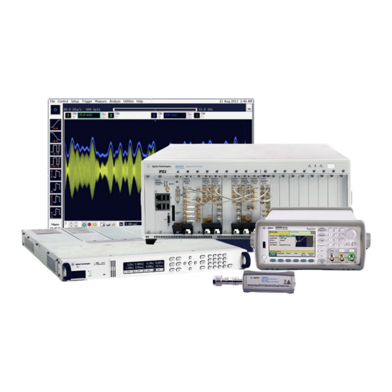
The synchronized signal with envelope is gen- erated by the Keysight M9381A Vector Signal Generator (VSG) and the Keysight 33522AWaveform Generator (AWG), passed to the DUT, and analyzed by the M9391A Vector Signal Analyzer (VSA). High meas- urement throughput is achieved with the fastune technology and embedded measurements associated with the PXIe VSG and VSA. - Page 8 Introduction Block Diagram Chassis and Modules RF PA Test, Reference Solution...
-
Page 9: Related Documentation
Introduction Related Documentation The documentation associated with this solution is available at the respective product pages on keysight.com (go to Document Library > Manuals). M9381A Vector Signal Generator (see www.keysight.com/find/M9381A) M9381A VSG and M9391A VSA Startup Guide M9381A VSG and M9391A VSA Programming Guide... -
Page 10: Items You Will Need
Step 6: Make a Measurement (page 30). If you are using a signal generator other than the Keysight M9381A PXIe Vector Signal Gen- erator the cable end at the signal generator RF Output may be different. RF PA Test, Reference Solution... - Page 11 Introduction RF PA Test, Reference Solution...
-
Page 12: Step 1: Unpack And Inspect The Rf Pa Test Solution Components
(see warranty information at begin- ning of this document). www.keysight.com/find/tips for information on preventing damage to your keysight equipment. Return an Instrument for Service Should it become necessary to return an instrument for repair or service, follow the steps below: All component modules for an M9381A M9391A instrument are factory tested, aligned, calibrated and shipped as a "bundle". -
Page 13: Verify Shipment Contents
Step 1: Unpack and Inspect the RF PA Test Solution Components 2. Contact Keysight to obtain a Return Material Authorization (RMA) and return address. For assistance finding contact information, go to www.keysight.com/find/assist. 3. Write the following information on a tag and attach it to the malfunctioning equipment: Name and address of owner. -
Page 14: Step 2: Install The Pxi Modules
Select a chassis that provides thermal protection if fans become inoperable or forced air cooling is obstructed Use slot blockers (Keysight model Y1212A, 5 per kit) and EMC filler panels in empty module slots to ensure proper operating temperatures. Keysight chassis... - Page 15 When you need to disconnect push-on cables from the module front panel con- nectors, use the Keysight Cable Removal Tool provided in your Keysight PXI instru- ment's ship kit. To avoid damage to the cables or con- nectors, pull the cable straight away from the connector.
-
Page 16: Prepare The Chassis
Install the Controller Use the appropriate instructions below for installing the embedded controller (Keysight models M9036A or M9037A) or remote controller (Keysight M9021A Cable Interface with M9045B adaptor for laptop PC or M9048A adaptor for desktop PC). Do not power up the controller until instructed to do so later in this document. - Page 17 Step 2: Install the PXI Modules Embedded Controller If your solution contains a Keysight M9036A or M9037A Embedded Controller, follow the pro- cedure below. (For additional detail, refer to instructions in the M9036A Startup Guide or the M9037A Startup Guide.) 1.
- Page 18 Step 2: Install the PXI Modules Remote Controller If your solutionn contains a Keysight M9021A Cable Interface Module, follow the procedure below. For addi- tional information about installing the M9021A, refer to the M9021A Installation Guide or the getting started video at http://www.youtube.com/watch?v=Idl02MF-nWU.
- Page 19 Step 2: Install the PXI Modules 4. On the M9021A module, set both S301 switches to the “Host” (right-hand) position and set the S201 rocker switch to the left-hand position. Refer to the following figure for M9021A switch locations and positions. 5.
-
Page 20: Install The M9381A And M9391A Instrument Modules
Step 2: Install the PXI Modules b. If you are using a desktop PC as a controller, connect to the M9021A using the following components: Install the M9381A and M9391A Instrument Modules Plan your module positions. Install the left-most module first and then continue installing modules from left to right according to the following photo. - Page 21 Step 2: Install the PXI Modules In the pictures below, you see two different routings of the 100 MHz Reference signal. The cabling on the left can be used for up to three M9393A instruments in one chassis. If you choose to install four M9393A instru- ments in one chassis, you may share the 100 MHz signal by using a tee at the 100 MHz In connector of the M9214A.The pictures on the next page show the recommended slot usage for multi-channel chassis and the recommended distribution of the 100 MHz reference.
-
Page 22: Install Slot Blockers And Filler Panels
It improves repeatability by enabling you to consistently measure the same portion of the input signal. Install Slot Blockers and Filler Panels To assure proper operating temperatures, install slot blockers (Keysight model Y1212A, 5 per kit) and EMC filler panels (Keysight model Y1213A, 5 per kit) in empty module slots. -
Page 23: Step 3: Install The Software
4 GB minimum (8 GB recommended for 64-bit operating systems) memory Available 1.5 GB available hard disk space (includes 1 GB for Microsoft .NET Framework 3.5 SP1 4, and 100 MB for Keysight IO Libraries disk space 3 Suite) Video... -
Page 24: Step 4: Redeem Your Software Licenses
* Software that is already installed if you ordered the M9036A or M9037A Embedded Controller. ** If you install or upgrade the Keysight 89600 VSA Software after installing the drivers, you need to run the 89600 VSA Integration utility. Go to Start > All Programs > Keysight> M9391 > 89600 VSA Integration. -
Page 25: Step 5: Verify Operation Of The M9381A Vector Signal Generator And M9391A Pxie Vector Signal Analyzer
2. The first step in this process is to conduct a Self Test of the M9381A and the M9391A. a. Open the M9381A SFP by selecting Start > All Programs > Keysight > M938x > M9381 SFP. b. Open the M9391A SFP by selectingStart > All Programs > Keysight > M9391 > M9391 SFP c. - Page 26 Step 5: Verify Operation of the M9381A Vector Signal Generator and M9391A PXIe Vector Signal Analyzer Selecting Connect initializes the instrument and all associated modules. Prior to initialization, all LEDs are off. RF PA Test, Reference Solution...
- Page 27 It is important that no signal is present at the RF Input of the Keysight M9350A PXIe Downconverter when doing a Self Test. If a signal is present, it may result in a false failure.
- Page 28 Return an Instrument for Service (page 12). It is important that no signal is present at the RF Input of the Keysight M9350A PXIe Downconverter when doing a Self Test. If a signal is present, it may result in a false failure.
-
Page 29: Communications
If not all modules and their slot locations are visible in the SFP "Connect to Instrument" dialog: 1. Close the SFP. 2. Start Keysight Connection Expert, by selecting Start > All Programs > Keysight Connection Expert. If any or all mod- ules and their slot locations are still not visible, select Refresh All. -
Page 30: Step 6: Make A Measurement
M9381A and the and press Connect. 2. Connect a high quality SMA (male) to SMA (male) cable between the RF Out connector on the Keysight M9310A PXIe Source Output and the RF In connector on the Keysight M9350A PXIe Downconverter. - Page 31 Step 6: Make a Measurement RF PA Test, Reference Solution...
- Page 32 Step 6: Make a Measurement 6. Below the display, select Continuous for a sustained sweep of the analyzer. You should see the following display on your M9391A SFP. The frequency of the signal is 2 GHz and the amplitude is -10 dBm. 7.
-
Page 33: Step 7: Verify Pa Test Configuration (Optional)
RF cable by configuring the settings in the user interface. Source code for the program can be provided. Contact your local Keysight representative to obtain the source code for the program. - Page 34 The M90XA X-App Software also requires licenses to run each X-App. The Power Amplifier Demo systems from Keysight include the required licenses. To obtain a temporary license to run the program on a non-Key- sight owned computer, please contact your local Keysight representative.
-
Page 35: Running The Power Amp Demo Program
Step 7: Verify PA Test Configuration (Optional) Running the Power Amp Demo Program The Power Amp Demo program provides a user interface to run the tests and display the results. The fol- lowing is a screen capture of the GUI after the program is launched. Tool tip help is available for each control in the demo program by hovering the mouse over that control. - Page 36 Step 7: Verify PA Test Configuration (Optional) The program saves test results and time data to a .CSV file. You can open the most recent data file by press- ing the Open Data Log button RF PA Test, Reference Solution...
-
Page 37: Configuring The Instruments
VISA resource string. For the power sensor, enter the VISA resource string if the calibration procedure will be run. The waveform generator and power sensor can be connected using USB. When using USB, use the Keysight Connection Expert to determine the VISA addresses for the instruments as shown in the following screen capture. - Page 38 Step 7: Verify PA Test Configuration (Optional) RF PA Test, Reference Solution...
-
Page 39: Basic System Test
Step 8: Installation is Complete Basic System Test The following procedure tests the connections and basic functionality of the Y1299A-002 basic system com- ponents. Pressing the INIT button in this procedure tests the connections and self tests of the M9381A VSG, M9391A VSA, and other standard Keysight equipment. - Page 40 Start > All Programs > Keysight IVI Drivers > AgM9391 VSA > Documentation. LabVIEW Driver In addition to the IVI drivers, Keysight provides a LabVIEW driver that includes all the functionality of the IVI- C driver. When you install the product software, the LabVIEW driver is installed to each LabVIEW instr.lib dir- ectory for each version of LabVIEW you have on your computer (for example, C:\Program Files (x86)\National Instruments\<LabVIEW version>\instr.lib\<Agilent product model>).
-
Page 41: Appendix: Troubleshooting
Connectivity. If the Keysight embedded controller is not being used, verify that the PC controller being used has been tested by Keysight. Many PCs cannot enumerate all the necessary PCIe slots required to support a full M9018A chassis. For details, consult the... -
Page 42: Diagnostic Flowcharts
Appendix: Troubleshooting Diagnostic Flowcharts Flowchart Use this flow when... Try This First (page You need to select which flowchart is most appropriate. PXI System Will Not Boot (page The PXI system does not power up as expected or appears to have no power. No Video Display (page The video display does not come up as expected. - Page 43 Appendix: Troubleshooting PXI System Will Not Boot RF PA Test, Reference Solution...
- Page 44 Appendix: Troubleshooting No Video Display RF PA Test, Reference Solution...
- Page 45 Appendix: Troubleshooting Basic Functional Check RF PA Test, Reference Solution...
- Page 46 Appendix: Troubleshooting PA Reference Solution RF PA Test, Reference Solution...
- Page 47 Appendix: Troubleshooting RF PA Test, Reference Solution...
Need help?
Do you have a question about the Y1299A-002 and is the answer not in the manual?
Questions and answers