Table of Contents
Advertisement
Quick Links
Advertisement
Table of Contents

Related Manuals for E-BLOX STEM CIRCUIT BUILDER 59


Summary of Contents for E-BLOX STEM CIRCUIT BUILDER 59
- Page 2 WARNING: unattended while the batteries are installed. Never connect additional batteries or any SHOCK HAZARD other power sources to your circuits. Discard any cracked or broken parts. Never connect E-Blox ® Circuit Adult Supervision: Builder to the electrical outlets in Because children’s abilities vary so much, even with age groups, adults should exercise discretion...
- Page 3 2. Be sure that parts with positive/negative markings are positioned as per the drawing. 3. Be sure that all connections are securely made. 4. Try replacing the batteries. Note: Rechargeable batteries do not work as well as alkaline batteries. E-Blox ® is not responsible for parts damaged due to incorrect wiring.
- Page 4 About Electricity 1. What is Electricity? 2. Who Discovered Electricity? Q: So many things are connected to electricity, such as Q: Who discovered electricity? lamps, TVs, and air conditioners. Can you tell me what A: I am going to tell you a story that can be traced back to at least electricity is? 600 BCE.
- Page 5 About Electricity 5. What did people do in electricity research? 6. Unit of Electricity Q: What did people do in electricity research after Miletus’ discovery? Q: What is the unit for electricity? A: Dating back to the 18th century, Benjamin Franklin, a famous American scientist, proved A: Electricity has various related units of measure.
- Page 6 About Electricity 9. What is Current? 10. What is Voltage? Q: What is current? Is that like water flow? Can it flow too? Q: What is voltage? A: Yeah, good question. Electric current can flow too, but it A: Voltage is equal to the work done per unit of charge against is totally different from water flow.
- Page 7 About Electricity 13. Power Supply 14. Switch A power supply is an electronic device that supplies electric A switch is a device that controls all the other components in the energy to an electrical load. The primary function of a power circuit.
- Page 8 Parts List Symbols and Numbers (colors and styles may vary) Important: If any parts are missing or damaged, DO NOT RETURN TO RETAILER. Call toll-free (855) MY EBLOX (693-2569) or e-mail us at: help@myeblox.com. Customer Service: 880 Asbury Dr., Buffalo Grove, IL 60089 U.S.A. Qty.
- Page 9 Parts List Symbols and Numbers (colors and styles may vary) Qty. Name Symbol Part # Qty. Name Symbol Part # Motor Alarm 6EB2X78 6EB2X64 Reed Motor 6EB2X83 6EB2X59 Switch Shaft Cap Magnet 6EB2X07 6EB2X60 Fiber Blade 6EB2X40 Optic Tree Motor 6EB2X95 Base 6EB2X39...
- Page 10 How to Use Your E-Blox ® Circuit Builder E-Blox ® Circuit Builder parts contain a PC board with You need a power source to build each connectors so you can build the different electrical and circuit. The part is marked 91 and electronic circuits in the projects.
- Page 11 About Your E-Blox ® Circuit Builder Parts (Part designs are subject to change without notice). The bi-directional LED (71) is like the others but has red and blue LEDs connected in opposite directions. The base grid functions like the printed circuit boards found in most electronic products.
- Page 12 You must be careful not to create “short circuits” (very low-resistance paths across the batteries, see examples below) as this will damage components and/or quickly drain your batteries. Only connect the parts using configurations given in the projects, incorrectly doing so may damage them. E-Blox ® is not responsible for parts damaged due to incorrect wiring.
- Page 13 The short circuit prevents any other portions of the circuit from ever working. NEVER DO THIS! NEVER DO NEVER DO THIS! THIS! WARNING: SHOCK HAZARD! Never connect E-Blox ® Circuit Builder to the electrical outlets in your home in any way! -12-...
- Page 14 Advanced Troubleshooting (adult supervision recommended) 4. Switch (62), Press switch (61), Reed Switch (83), E-Blox ® is not responsible for parts damaged due to 4-Wire Block (4): Use this circuit to test each switch and incorrect wiring. the wire blocks. The lamp (76) and bi-directional LED (71) If you suspect you have damaged parts, you can should light.
-
Page 15: Table Of Contents
Project Listings Description Page Description Page 1. LED Switch 31. Switch-controlled Fan & Lamp Series Connection 2. LED Press Switch 32. Switch-controlled Motor & Alarm Series Connection 3. Magnet-controlled LED 33. Switch-controlled Alarm & LED Series Connection 4. Lamp Switch 34. -
Page 16: Led Switch
1. LED Switch E-Blox ® Circuit Builder uses electronic blocks that plug onto a clear plastic grid to build different circuits. These blocks have different colors and numbers on them so that you can easily identify them. Build the circuit shown on the left by placing all the parts that plug onto the first layer base. -
Page 17: Magnet-Controlled Led
3. Magnet-controlled LED Build the circuit, move the magnet (7) towards the reed switch (83), the LED (69) will turn on, move the magnet (7) away, and the LED (69) will turn off. 4. Lamp Switch Build the circuit, press the switch (62), the lamp (76) will turn on. -
Page 18: Press Switch-Controlled Lamp
5. Press Switch-controlled Lamp Build the circuit, press the press switch (61), the lamp (76) will flash. Hold the press switch (61), the lamp (76) will stay 6. Magnet-controlled Lamp Build the circuit, move the magnet (7) towards the reed switch (83), the lamp (76) will turn on. -
Page 19: Bi-Directional Led Switch
Red Light 7. Bi-directional LED Switch Build the circuit, press the switch (62), you will see the bi-directional LED (71) turn on blue. Install the bi-directional LED (71) in the reverse direction. When you press the switch (62) the bi-directional LED (71) will turn on red. -
Page 20: Magnet-Controlled Bi-Directional Led
9. Magnet-controlled Red Light Bi-directional LED Build the circuit, move the magnet (7) towards the red switch (83), the bi- directional LED (71) will turn on blue. Move the magnet (7) away, the light will turn off. Install the bi-directional LED (71) in the reverse direction, then move the magnet (7) towards the reed switch (83), the bi- directional LED (71) will turn on red. -
Page 21: Press Switch-Controlled Alarm
11. Press Switch-controlled Alarm Build the circuit, press the press switch (61), you will hear the alarm (78) sound. Hold the press switch (61), the alarm (78) will stay on. 12. Magnetic-controlled Alarm Build the circuit, move the magnet (7) towards the reed switch (83), the alarm (78) will sound. -
Page 22: Switch-Controlled Fiber Optic Tree
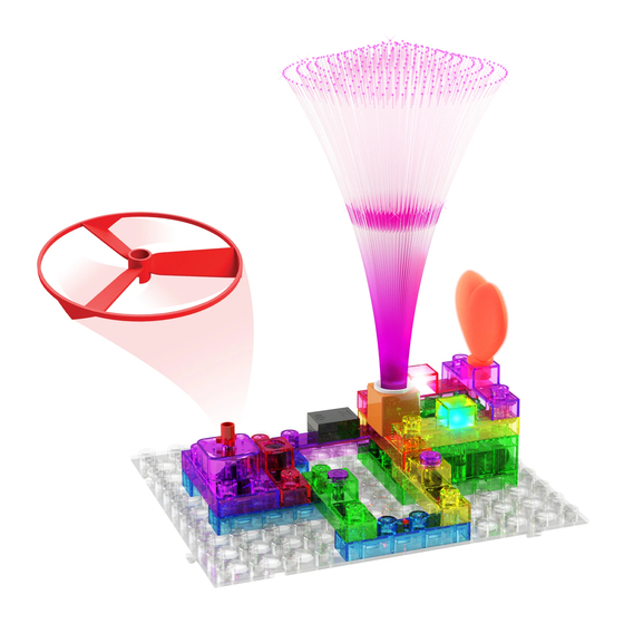
13. Switch-controlled Fiber Optic Tree Build the circuit and place the fiber optic tree on the colorful LED (72), press the switch (62), the colorful LED (72) will turn on, you will see the fiber optic tree (40) change colors with the LED’s colors. 14. -
Page 23: Magnet-Controlled Fiber Optic Tree
15. Magnet-controlled Optical Fiber Tree Build the circuit, move the magnet (7) towards the reed switch (83), the colorful LED (72) will turn on, the fiber optic tree (40) is changing colors with the colorful LED (72). 1st level 16. Motor Switch Build the circuit, press the switch (62), the motor (95) will turn on. -
Page 24: Press Switch-Controlled Motor
17. Press Switch-controlled 1st level Motor Build the circuit, press the press switch (61), the motor (95) will turn on for a short time. Hold the press switch (61), the motor (95) will stay on. WARNING: Moving parts. Do not touch the fan or motor during operation. -
Page 25: Switch & Press Switch-Controlled Led Series Connection
19. Switch & Press Switch- controlled LED Series Connection Build the circuit, press the switch (62), then hold the press switch (61). The LED (69) will turn on. Release the press switch (61), then the light will turn off. 20. Switch & Press Switch- controlled Lamp Series Connection Build the circuit, press the switch (62),... -
Page 26: Switch & Press Switch-Controlled Bi-Directional Led Series Connection
21. Switch & Press Switch- Red Light controlled Bi-directional LED Series Connection Blue Light Build the circuit, press the switch (62), then hold the press switch (61), the bi- directional LED (71) will turn on blue. Release the press switch (61), then install the bi-directional LED (71) in the reverse direction, hold the press switch (61) the bi-directional LED (71) will turn on red. -
Page 27: Switch & Press Switch-Controlled Motor Series Connection
23. Switch & Press Switch- controlled Motor Series Connection Build the circuit, press the switch (62), then hold the press switch (61). The motor (95) will turn on. Release the press switch (61), then the motor (95) will turn off. WARNING: Moving parts. -
Page 28: Magnet, Switch & Press Switch-Controlled Led Series Connection
25. Magnet, Switch & Press Switch-controlled LED Series Connection Build the circuit, press the switch (62), then hold the press switch (61). Then move the magnet (7) towards the reed switch (83), you will see the LED (69) turn on. If you move the magnet (7) away, the LED (69) will turn off. -
Page 29: Magnet, Switch & Press Switch-Controlled Fiber Optic Tree Series Connection
27. Magnet, Switch & Press Switch-controlled Fiber Optic Tree Series Connection Build the circuit, press the switch (62), then hold the press switch (61). Move the magnet (7) towards the reed switch (83). The colorful LED (72) will turn on. The fiber optic tree (40) will light up with the colors of the LED. -
Page 30: Magnet, Switch & Press Switch-Controlled Alarm Series Connection
29. Magnet, Switch & Press Switch-controlled Alarm Series Connection Build the circuit, press the switch (62), then hold the press switch (61). When you move the magnet (7) towards the reed switch (83), you will hear the alarm (78). If you move the magnet (7) away, the alarm (78) will turn off. -
Page 31: Switch-Controlled Fan & Lamp Series Connection
31. Switch-controlled Fan & Lamp Series Connection Build the circuit, press the switch (62), the fan blade (60) of the motor (95) will start running while the lamp (76) is on. Fan Assembly Motor shaft cap Motor top WARNING: Moving parts. Do not touch the fan or motor during operation. -
Page 32: Switch-Controlled Alarm & Led Series Connection
33. Switch-controlled Alarm & LED Series Connection Build the circuit, press the switch (62), you will hear the alarm (78), while the LED (69) turns on at the same time. 34. Press Switch-controlled Alarm & LED Series Connection Build the circuit, press the press switch (61) several times, the alarm (78) will sound for short intervals. -
Page 33: Magnet-Controlled Alarm & Led Series Connection
35. Magnet-controlled Alarm & LED Series Connection Build the circuit, move the magnet (7) towards the reed switch (83), the alarm (78) will sound while the LED (69) is on. Move the magnet (7) away, the alarm (78) and LED (69) will turn off. 36. -
Page 34: Magnet & Switch-Controlled Fan
37. Magnet & Switch-controlled Fan Build the circuit, press the switch (62), when you move the magnet (7) towards the reed switch (83), you will see the fan blade (60) of the motor (95) start spinning. When you move the magnet (7) away, the fan blade (60) will stop spinning. -
Page 35: Press Switch-Controlled Lamp Alarm
40. Press Switch-controlled Lamp Alarm Build the circuit, press and hold the press switch (61), you will hear the alarm (78) sound, while the lamp (76) will light dimly. When you release the press switch (61), the alarm (78) will stop. The lamp is used as a wire block in this circuit and will light dimly. -
Page 36: Switch-Controlled Alarm & Lamp Series Connection
42. Switch-controlled Alarm & LED Series Connection Build the circuit, press the switch (62), the alarm (78) will start in a low volume, while the LED (69) turns on. 43. Press Switch-controlled Alarm & LED Build the circuit, hold the press switch (61), the alarm (78) will start in a low volume, while the LED (69) turns on. -
Page 37: Magnet-Controlled Alarm & Led
44. Magnet-controlled Alarm and Build the circuit, move the magnet (7) towards the reed switch (83), the alarm (78) will start in a low volume while the LED (69) turns on. If you move the magnet (7) away, the alarm (78) and LED (69) will turn off. -
Page 38: Press Switch-Controlled Bi-Directional Led & Alarm
46. Press Switch-controlled Bi- directional LED & Alarm Build the circuit, hold the press switch (61), you will hear the alarm (78) sound, while the bi-directional LED (71) turns on red. Release the press switch (61), then install the bi-directional LED (71) in the reverse direction. -
Page 39: Switch-Controlled Fiber Optic Tree & Alarm Series Connection
48. Switch-controlled Fiber Optic Tree & Alarm Series Connection Build the circuit, press the switch (62), the alarm (78) will sound very faintly. Then you will see the colorful LED (72) turn on. The fiber optic tree (40) will be lit up with the colors of the LED. -
Page 40: Magnet-Controlled Fiber Optic Tree & Alarm Series Connection
50. Magnet-controlled Fiber Optic Tree & Alarm Series Connection Build the circuit, move the magnet (7) towards the reed switch (83), the alarm (78) will sound very faintly. Then you will see the fiber optic tree (40) turn on with the light of the colorful LED (72). -
Page 41: Magnet & Switch-Controlled Alarm & Led Series Connection
52. Magnet & Switch-controlled Alarm & LED Series Connection Build the circuit, first press the switch (62), then move the magnet (7) towards the reed switch (83), you will hear the alarm (78) sound very faintly. The LED (69) will turn on at the same time. -
Page 42: Magnet, Switch & Press Switch-Controlled Alarm & Lamp Series Connection
54. Magnet, Switch & Press Switch-controlled Alarm & Lamp Series Connection Build the circuit, press the switch (62), then hold the press switch (61). Move the magnet (7) towards the reed switch (83), you will hear the alarm (78) sound while the lamp (76) is still off. -
Page 43: Magnet, Switch & Press Switch-Controlled Alarm & Motor Series Connection
56. Magnet, Switch & Press Switch-controlled Alarm & Motor Series Connection Build the circuit, press the switch (62), then hold the press switch (61). Move the magnet (7) towards the reed switch (83), you will hear the alarm (78) sound very faintly while the motor (95) is off. -
Page 44: Press Switch-Controlled Led & Bi-Directional Led Series Connection
Red Light Blue Light 58. Press Switch-controlled LED & Bi-directional LED Series Connection Build the circuit, press and hold the press switch (61), you will see the LED (69) and the bi- directional LED (71) turn on red at the same time. Install the bi-directional LED (71) in the reverse direction, then press the press switch (61), the LED (69) will turn on red, while the bi-directional LED (71) will turn on blue. -
Page 45: Magnet-Controlled Led & Bi-Directional Led Series Connection
Red Light Blue Light 59. Magnet-controlled LED and Bi-directional LED Series Connection Build the circuit, move the magnet (7) towards the reed switch (83), you will see the LED (69) and the bi-directional LED (71) turn on red. Move the magnet (7) away and install the bi-directional LED (71) in the reverse direction. - Page 46 Your E-Blox ® Circuit Builder is compatible with other E-Blox ® products! Your E-Blox ® Circuit Builder kit includes two tin plated blocks (part # 6EB2X101) which allow you to connect to other E-Blox ® sets. A simple demo circuit is shown on the right and the parts needed to build it are shown below.
- Page 47 Other E-Blox ® Products ™ ™ Follow adventures Seymour and his robot Robyn as they investigate a mysterious light distant ocean horizon. The storybook includes codes that create interactive learning environment using online resources. Models Build 115 projects with component...
Need help?
Do you have a question about the STEM CIRCUIT BUILDER 59 and is the answer not in the manual?
Questions and answers