Advertisement
Quick Links
1.1
General
Allgemeines
1.2
Technical
Technischen
specifications
Daten
1.3
Dimensions
Maßskizzen
and
und
specifications
technical
data
1.4
Installation
Installation
1.5
Operation/
Inbetrieb-
Failure
nahme/
diagram/
Störungs-
Electric
diagramm/
diagram
Elektrisch
Schema
1.6
Maintenance
Wartung
1.7
Equipment
Beschreibung
description
der
Komponenten
TECHNISCHES HANDBUCH
G A S F I R E D
W A L L - M O U N T E D
G A S B E F E U E R T E
TECHNICAL MANUAL
Type GSE– (Closed unit)
Type GSE–O (Open unit)
Typ GSE– (Geschlossene Ausführung)
Typ GSE–O (Offene Ausführung)
U N I T
H Ä N G E N D E
L U F T E R Z E U G E R
A I R
H E A T E R
33–08
Advertisement

Subscribe to Our Youtube Channel
Related Manuals for Mark GSE Series


Summary of Contents for Mark GSE Series
- Page 1 TECHNICAL MANUAL TECHNISCHES HANDBUCH Type GSE– (Closed unit) Type GSE–O (Open unit) Typ GSE– (Geschlossene Ausführung) Typ GSE–O (Offene Ausführung) General Allgemeines Technical Technischen specifications Daten Dimensions Maßskizzen specifications technical data Installation Installation Operation/ Inbetrieb- Failure nahme/ diagram/ Störungs- Electric diagramm/ diagram Elektrisch...
- Page 2 1.1.1 1.1.2 1.1.3...
-
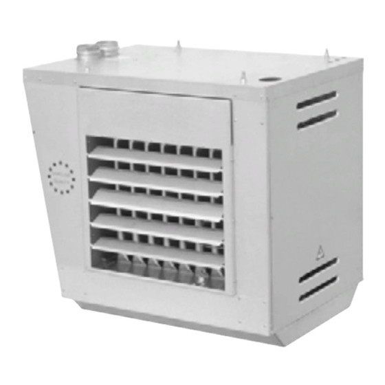
Page 3: General Allgemeines
General Allgemeines 1.1.1 4 fixing points M 10 4 Aufhängepunkte M 10 Entry hole for gas- and electrical Durchführungen für den Gasanschluß und connections elektrische Anschlüsse (topside only) (nur an der Oberseite) Heat exchanger (chrome steel) Wärmetauscher (Chrom Stahl) Housing (Aluzinc) Gehäuse (Aluzink) Adjustable discharge louvres (horizontal) Einstellbare Ausblaslamellen (horizontal) - Page 4 1.2.1 – – 1.2.2 m3/h dB(A) 20,4 22,7 2190 21,8 24,2 2190 25,1 27,9 2730 27.2 30,2 2730 30,2 33,5 3320 32,7 36,3 3320 40,2 44,7 4425 43,6 48,4 4425 50,2 55,8 5525 54,5 60,5 5525 60,3 67,0 6635 65,3 72,6 6635 80,4...
- Page 5 Technical specications Technischen Daten 1.2.1 Model description: Typenerklärung: Axial-flow fan Axialventilator Electronic ignition Elektronische Zündung Type Typ (Gerätegröße) GSE-- Closed unit GSE-- Geschlossene Ausführung GSE--O Open unit GSE--O Offene Ausführung CODIFICATION / DESCRIPTION KODIERUNG / UMSCHREIBUNG 1.2.2 Type Typ (Gerätegröße) Rated output Nennwärmeleistung Rated input...
- Page 6 1.3.1 GSE-O 1.3.2 4H/4V 18/21 24/28 33/37 44/49 55/59 66/74 1110 88/104 1120 1370 1145 1.3.3.1 1.3.3.2 GSE-O 1.3.4 GSE-O C => E => F => F =< G => H => P => R => R =< 18/21 2800 1115 2800 24/28...
- Page 7 Dimensions and technical data Maßskizzen und technischen Daten 1.3.1 Vertical louvre assembly (option) Ausblasgitter mit senkrechten Lamellen (Option) Doppelrichtungskopf 2x 45° mit waage- Two-way diffuser with horizontal louvres rechten Lamellen (Option) (option) Doppelrichtungskopf 2x 45° mit senk- Two-way diffuser with vertical louvres rechten Lamellen (Option) (option) 23A Satz Aufhängekonsolen (Option)
- Page 8 1.3.5 = BE; CZ; NL: 50 mbar = AT; DE: 50 mbar BE; NL AT; BE; CZ; DE; DK; ES; FL; FR; GB; = FR; GB; HU; IE; IT; = DK; ES; FI; GR; NO; SE: 30 mbar GSE-O GR; HU; IE; IT; LU; PL; PT; SE LU;...
- Page 9 Dimensions and technical data Maßskizzen und technischen Daten 1.3.5 Gastechnical data: Gastechnische Daten: Type Typ (Gerätegröße) Rated output Nennwärmeleistung Rated output Nennwärmebelastung Burnerpressure difference Düsendruck Differenz GSE-O Gasconsumption Gasmenge Injector diameter main burner Düsendurchmesser Hauptbrenner When type 104 Low NOx. GSE-21 O nicht lieferbar als Low NOx GSE-21 O not available as Low NOx Gerät.
- Page 10 1.3.6.2 C 12 C 32 1.3.6.3 GSE-O 18/28 33/98...
- Page 11 Dimensions and technical data Maßskizzen und technischen Daten 1.3.6.2 Flue gas outlet and air supply: Zuluft / Abgasführung: C32 Flue system. C32 Abgassystem (Doppelrohr über Dach). The maximum length L of the supply and outlet piping Die Höchstlänge L der Zuluft- und Abgasleitungen is six metres, included two elbows of 90°...
- Page 12 1.3.7 øD 1028 1078 1570 1028 1078 1570 1028 1078 1570 1028 1078 1570 øD 1028 1078 1570 1028 1078 1570 1028 1078 1570 øD 1028 1078 1570 øD 1016 1096 1570 1016 1096 1570 1016 1096 1570 1016 1096 1570 1016 1096...
- Page 13 Dimensions and technical data Maßskizzen und technischen Daten 1.3.7 Flue gas outlet and air supply: Zuluft / Abgasführung: C32 Flue system. C32 Abgassystem (Doppelrohr über Dach). Dimensions of flue system through the roof. Abmessungen Dachdurchlaß. Advice: Ratschlag: Place orifice D in the combustion air intake if Durchm.
- Page 14 1.3.10 a...
- Page 15 Maßskizzen und technische Daten 1.3.10 a Düsendruckgrafik WLE typ 18, 24, 33, 44, 55, 66, 88.
- Page 16 1.3.10 b...
- Page 17 Maßskizzen und technische Daten 1.3.10 b Düsendruckgrafik WLE typ 21, 28, 37, 49, 59, 74, 98.
-
Page 19: Installation
Installation Installation 1.4.1 Check the unit for damage after unpacking. Nach dem Auspacken ist das Gerät auf mögliche Beschädigung zu überpüfen. Check whether the type/model and power supply volt- age are correct (230 Volt). Prüfen Sie, ob Modell/Typ und elektrische Spannung korrekt sind (230 Volt). - Page 20 1.5.1 1.5.2.2 GSE-O...
- Page 21 Operation Inbetriebname Inspection activities: Kontrollarbeiten 1.5.1 a. Switch off the main switch. a. Netzschalter ausschalten. b. Set room thermostat at minimum temperature. b. Raumthermostat auf die Mindesttemperatur einstellen. c. Open the gas shut-off valve, carefully vent and c. Den Gasabsperrhahn öffnen und anschließend check the gas lines for leakage with soapy water die Gasleitungen sorgfältig entlüften und mittels Never use open flame...
- Page 22 1.5.3.1 06 29 048 230 V 1.5.3.2 06 29 048 230 V...
- Page 23 Operation Inbetriebname 1.5.2.3 Check the function of the room thermostat. Die Funktion des Raumthermostates ist zu prüfen; ist The main burners must go out at a temperature setting der Sollwert niedriger als die Umgebungstemperatur, below the ambient temperature. sollte der Brenner ausgehen. Ist der Sollwert höher als The burners must go on again at a setting above the die Umgebungstemperatur, so werden die Brenner wie- ambient temperature.
- Page 24 Trouble shooting diagramm (GSE) Trouble shooting diagramm GSE with SIT EFD...
- Page 25 Electrical diagramm (GSE)
- Page 26 Trouble shooting diagramm (GSE-O) Trouble shooting diagramm GSE-O uniheaters with SIT EFD...
- Page 27 Electrical diagramm (GSE-O)
- Page 28 Störungsdiagramm (GSE) Störungsdiagramm GSE mit SET EFD Feuerungsautomaten...
- Page 29 Verdrahtungsplan (GSE)
- Page 30 Störungsdiagramm (GSE-O) Störungsdiagramm GSE-O mit SET EFD Feuerungsautomaten...
- Page 31 Verdrahtungsplan (GSE-O)
- Page 32 1.6.1 C/G/L 1.6.1.5 D/H/M 1.6.1.6...
- Page 33 Maintenance Wartung 1.6.1 Maintenance: Wartung: At least once a year or more frequently, if required: Gasgeräte müssen mindestens einmal im Jahr gewartet werden: 1.6.1.1 Clean the burner box: remove the inspection cover Das Brennerbett kann gereinigt werden, indem der with sight glass, slide out the burner box, blow the Inspektionsdeckel mit Schauglas entfernt und der burners through with compressed air from the top, Brennerschlitten heraus gezogen wird.
- Page 34 1.7.1 CODE CODE 18/21 SIT 830 TANDEM 06 08 082 SIT EFD 503 06 08 058 24/28 SIT 830 TANDEM 06 08 082 SIT EFD 503 06 08 058 33/37 SIT 830 TANDEM 06 08 082 SIT EFD 503 06 08 058 GSE-O 44/49 SIT 830 TANDEM...
- Page 35 Equipment descriptions Beschreibung der Komponenten 1.7.1 Type Gerätegröße (Typ) Gas combination valve Gasmagnetventil: Burner control Brennersteuergerät Natural gas Geräte für Erdgas Only for NL, BE and DE. Nur für NL, BE und DE. GSE-O 1.7.1.1 Gas control Gasreglerkombination Gas control system for fully automatic control and Gasreglerkombination zum automatischen Regeln protection of gas-fired heating units with electronic und Überwachen von einem Warmlufterzeuger.
- Page 36 18/59 66/104 Reset Reset 1.7.3 GSE-O 30 22 810 30 22 815 1.7.3.1 GSE-O 31 01 930 MAX I (°C) MAX II (°C) 1.7.3.2 18/21 24/28 33/37 44/49 55/59 66/74 GSE-O 31 01 935 1.7.3.3 GSE-O 06 29 033 1.7.3.4 06 07 604 03-1373...
- Page 37 Equipment descriptions Beschreibung der Komponenten Thermostat combination Thermostatenkombination 1.7.3 The thermostat contens: Die Thermostatkombination besteht aus: one fan thermostat einem Minimalthermostat one unit thermostat einem Maximalthermostat one safety thermostat (STB) einem Sicherheitsthermostat (STB) GSE-O Sizes 18/59 have one maximum thermostat. Die Geräten 18/59 haben ein C/D Sizes 66/104 are provided with two maximum Maximalthermostat.
- Page 38 1.7.3.5 code 18/37 31 03 275 44/59 31 03 276 66/104 31 03 277 1.7.3.6 GSE-O code 18/28 31 09 001 33/37 31 09 002 44/49 31 09 003 55/59 31 09 004 66/74 (2x) 31 09 002 88/104 (2x) 31 09 003...
- Page 39 Equipment descriptions Beschhreibung der Komponenten 1.7.3.5 Repairkit Fluefan Austauschsatz Abgasventilator motor Motor fan-wheel Laufrad gasket Dichtung gasketring Dichtungsringe sticker with rotation direction Aufkleber Drehrichtung coolingplate Kühlplatte moutingplate motor Motorgrundplatte not for GSE-O nicht für GSE-O 1.7.3.6 Exchangekit axial fan: Ersatz Umluftventilator: fan motor Ventilatormotor protection guard...
Need help?
Do you have a question about the GSE Series and is the answer not in the manual?
Questions and answers