
Summary of Contents for Remote Control Technology Muirhead 11337
- Page 1 PRODUCT MANUAL POWER MODE BYPASS CONTROLLER TO SUIT KOMATSU HD785-5 AND HD785-7 VEHICLES Part No. 11337 | 12731...
- Page 2 DISCLAIMER © Remote Control Technologies Pty Ltd. ■ No part of this manual may be reproduced, copied, translated, or transmitted in any form or by any means without the written permission of RCT. ■ Information provided in this manual is intended to be accurate and reliable. However, RCT assumes no responsibility for its use or infringements upon the rights of third parties that may result from its use.
-
Page 3: Table Of Contents
Contents GENERAL SAFETY WARNINGS PRODUCT OVERVIEW FEATURES AND FUNCTIONS OPERATION AND USE CONTROLLER STATUS INDICATOR OPERATION INSTALLATION GUIDE INSTALLATION FOR KOMATSU HD785-5 WIRING CONNECTIONS INSTALLATION FOR KOMATSU HD785-7 WIRING CONNECTIONS DIAGRAMS WIRING DIAGRAM TO SUIT KOMATSU HD785-5 (519c) WIRING DIAGRAM TO SUIT KOMATSU HD785-7 (519d) WIRING DIAGRAM TO SUIT KOMATSU HD465 AND HD605 (590a) CALIBRATION SERVICE INFORMATION... -
Page 4: General Safety Warnings
GENERAL SAFETY WARNINGS PERSONAL SAFETY ■ Everyone is responsible for safety. ■ The installer/service personnel should be trained and authorized to complete the required work. ■ Ensure that the machine is safely isolated during installation and testing to protect all personnel. ■... -
Page 5: Product Overview
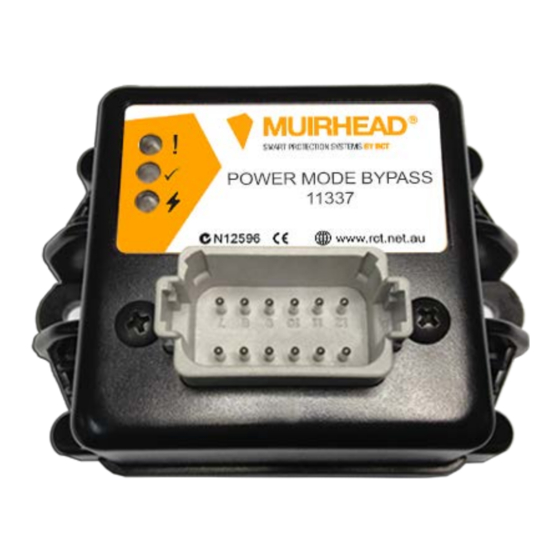
PRODUCT OVERVIEW ® The Muirhead Power Mode Bypass Controller, part number 11337, is designed to automatically select either standard mode or power mode based on whether or not the tray is loaded. FEATURES AND FUNCTIONS ■ Multi-voltage 12-24 V Environmentally sealed – IP65 ■... -
Page 6: Controller Status Indicator Operation
CONTROLLER STATUS INDICATOR OPERATION STATE INDICATOR SEQUENCE ■ Battery Power-up All indicators will turn on. ■ All indicators will turn off. ■ After power-up, the controller will revert to normal operation. Status Indicator in RED – Fault. Operation ■ If outputs have problems, this will turn on. ■... -
Page 7: Installation Guide
INSTALLATION GUIDE Install the controller in a suitable location, preferably in the cabin. Refer to the wiring table below and the wiring diagram in this manual to connect the controller. It is recommended that the wiring is installed alongside the OEM wiring ensuring that it is secured at regular intervals;... -
Page 8: Installation For Komatsu Hd785-7
INSTALLATION FOR KOMATSU HD785-7 Connect wiring as per 519d and as follows: WIRING CONNECTIONS COLOUR FUNCTION DESCRIPTION Battery +VE Connect to a protected 12–24 V battery Black Ground Connect to ground/battery negative Yellow/Blue Connect to the wire that was disconnected from pin 6 Output 1 of the OEM power mode switch Green... -
Page 9: Diagrams
DIAGRAMS WIRING DIAGRAM TO SUIT KOMATSU HD785-5 (519c) (11110) (11981) 1.2 K 9 | 16 M0698.docx | Rev 2.3 | Modified on 29/09/2017 | © Remote Control Technologies Pty Ltd... -
Page 10: Wiring Diagram To Suit Komatsu Hd785-7 (519D)
WIRING DIAGRAM TO SUIT KOMATSU HD785-7 (519d) PWM2_M (11110) (11981) 1.2K 10 | 16 M0698.docx | Rev 2.3 | Modified on 29/09/2017 | © Remote Control Technologies Pty Ltd... -
Page 11: Wiring Diagram To Suit Komatsu Hd465 And Hd605 (590A)
WIRING DIAGRAM TO SUIT KOMATSU HD465 AND HD605 (590a) PWM_M (11110) (11981) 1.2K 11 | 16 M0698.docx | Rev 2.3 | Modified on 29/09/2017 | © Remote Control Technologies Pty Ltd... -
Page 12: Calibration
CALIBRATION SETTING NO. DESCRIPTION UNITS* DEFAULT Override Time Seconds The length of time the economy bypass switch will allow the unit to force power mode, adjustable between 0 and 3 minutes. Truck Load Time Seconds The length of time the controller will wait to engage power mode once the correct weight has been sensed (this is used to stop false changes), adjustable between 0 and 30 seconds. -
Page 13: Parts List
PARTS LIST 12731 POWER ECONOMY BYPASS KIT QUANTITY PART NO. DESCRIPTION INCLUDED SUGGESTED PARTS SPARES 11337 Power mode bypass controller 11110 Green LED 11981 LED resistor 12731 Power economy bypass kit 12738 Generic loom 7919 Bypass switch 3214 Switch cover 13617 System override label TECHNICAL SPECIFICATIONS... -
Page 14: Compliance And Standards
COMPLIANCE AND STANDARDS Remote Control Technologies Pty Ltd has an obligation as a manufacturer to comply with the regulations as required by the relevant regulatory bodies, depending on the market and location. This product currently complies with the following: ACMA ■... -
Page 15: Glossary
GLOSSARY Amp (Ampere) Milli Watts Alternating Current Not Applicable Advanced Management System Normally Closed Auxiliary Output Normally Open Controller Area Network Original Equipment Manufacturer CMIO Control Master Input Output PCB Outputs Control Master Receiver Output Control Master Transmitter Push Button CM2200 Control Master 2200 Remote Set Personal Computer... - Page 16 Discover more: www.rct-global.com sales@rct-global.com AUSTRALIA: +61 (0) 8 9353 6577 AFRICA: +27 (0) 83 292 4246 CANADA: +1 705 590 4001 RUSSIA / CIS: +7 (910) 411 11-74 SOUTH AMERICA: +56 9 7387 2385 USA: +1 801 938 9214...
Need help?
Do you have a question about the Muirhead 11337 and is the answer not in the manual?
Questions and answers