Advertisement
Quick Links
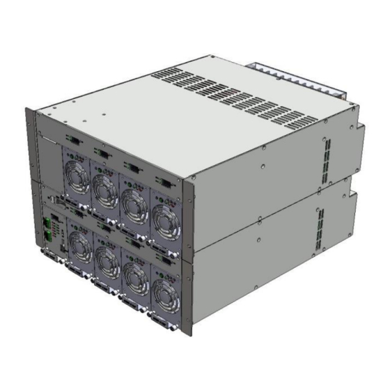
DCPS-FRS-2421K Operation Manual
DCPS-FRS-2421K Rectifier Shelf and
DCPS-FRS-2421KE Expansion Shelf
• AC Input: 1Phase 3Wire (range: 93V~275V)
• DC Output: 27V @ 400A (up to 800A with stacked DCPS-FRS-2421KE Expansion Shelf)
• Hot-swappable 100A Rectifier Modules with individual Load Voltage and Current meters in Shelf
The Appendix within this User Manual contains supporting documents including datasheets
for the DCPS-FRS-2421K Rectifier Shelf, modules, and other useful reference material
Components of the DCPS-FRS-2421K Shelf
DCPS-FRC-2421K
Control Module
DCPS-NDRM-2100F
Rectifier Module
1
Advertisement

Subscribe to Our Youtube Channel
Summary of Contents for Eagle Eye Power Solutions DCPS-FRS-2421K
- Page 1 • Hot-swappable 100A Rectifier Modules with individual Load Voltage and Current meters in Shelf Components of the DCPS-FRS-2421K Shelf DCPS-NDRM-2100F DCPS-FRC-2421K Rectifier Module Control Module The Appendix within this User Manual contains supporting documents including datasheets for the DCPS-FRS-2421K Rectifier Shelf, modules, and other useful reference material...
- Page 2 Section 1. Shelf Overview The DCPS-FRS-2421K Rectifier (Main) Shelf is a 19-inch wide, 4RU height, intelligently-controlled +27V DC Output Rectifier Shelf. The DCPS-FRC-2421K Control Module interfaces with up to 4 DCPS-NDRM-2100F Rectifier Modules in the Main Shelf and 4 in an optional DCPS-FRS-2421KE Expansion Shelf).
- Page 3 -10°C to +55°C but power is derated above 50°C. AC Input Voltage Derating: The DCPS-FRS-2421K Rectifier (Main) Shelf is designed to operate inconditionswith the applied AC input voltage between 93Vac to 275Vac. Each DCPS-NDRM-2100F Rectifier Module iscapable ofproviding full DC Output power when the AC input voltage is 176V or higher.
- Page 4 Read and review all portions of this Operation Manual before attempting to touch, handle, connect-to or disconnect-from, configure, power up, power down, or make any measurements to or from this Rectifier Shelf. Eagle Eye Power Solutions, LLC | 877-805-3377 | www.eepowersolutions.com...
- Page 5 8) Output over voltage protection: Module OVP (shutdown) at > 31.0Vdc 9) Battery Low Voltage protection: LVD disconnects at 23.0V ±0.5V (ends battery discharge) 10) Output Ripple / Noise: ≤ 250mVpeak Table 1. DC Output Terminal Block assignments Eagle Eye Power Solutions, LLC | 877-805-3377 | www.eepowersolutions.com...
- Page 6 Operating Humidity: 10% ∼ 95%, non-condensing Mechanical Dimensions DCPS-FRS-2421K (Main) Shelf ⇒ 177mm (H) X 482.6mm (W) X 555mm (D) ⇒ 6.97in. (H) X 19.0in. (W) X 21.85in. (D) DCPS-FRS-2421KE (Expansion) Shelf ⇒ 177mm (H) X 482.6mm (W) X 555mm (D) ⇒...
- Page 7 When work is completed or the shelf will be left unattended, always replace the protective covers over the terminal blocks. Figure 2. Output Terminal Block Cover Eagle Eye Power Solutions, LLC | 877-805-3377 | www.eepowersolutions.com...
- Page 8 P.E. (Protective Earth Ground) : 3.5mm (AWG 12) *Use M4 lug Communication Ground min. 8mm (AWG 3/0) *Use M6 lug Figure 3. AC Input, Output, & Ground connections for Main and Expansion Shelf Eagle Eye Power Solutions, LLC | 877-805-3377 | www.eepowersolutions.com...
-
Page 9: Rear View
Battery String. The B-TEMP probe and should be mounted on the top-central portion of the Battery String. BATT- +27V BATT+ DC Output ports B- TEMP R- TEMP Rear View Figure 4. Output Cable Connection – Rectifier (Main) shelf Eagle Eye Power Solutions, LLC | 877-805-3377 | www.eepowersolutions.com... - Page 10 Blank Cover for any Expansion empty Rectifier Shelf Module position Blank Cover for Main empty position Shelf (no Control Module in Expansion Shelf) Figure 4a. Expansion Shelf mated with Main Shelf Eagle Eye Power Solutions, LLC | 877-805-3377 | www.eepowersolutions.com...
- Page 11 Access Covers (shown removed) from bottom of Expansion Shelf Access Covers (not yet removed) from top of Main Shelf Figure 4b. Blank Panel Figure 4d. Access Covers for Cable and Bus Bars Eagle Eye Power Solutions, LLC | 877-805-3377 | www.eepowersolutions.com...
- Page 12 Use a Module Filler for each module position that will not be filled with a Rectifier Module. Shelf Assembly is complete and ready for Shelf Power-up Procedure. Proceed to Section 3.4. Figure 4f. Shelf Locations for Figure 4e. Rear Covers Bus Bars and Cable Eagle Eye Power Solutions, LLC | 877-805-3377 | www.eepowersolutions.com...
- Page 13 Power-Up procedure completed. Proceed to Section 4 to be- gin working with the Graphical User Interface (GUI). Figure 4g. Fully configured DCPS-FRS-2421K (Main) & DCPS-FRS-2421KE (Expansion) Eagle Eye Power Solutions, LLC | 877-805-3377 | www.eepowersolutions.com...
- Page 14 System Operation Controller Manager System Configuration Measurement Set Date/Time Set Controller Set Factory Initalization Alarm Log, Data Log, and Event Log Exiting the GUI Eagle Eye Power Solutions, LLC | 877-805-3377 | www.eepowersolutions.com...
- Page 15 GUI Login process, ensure that the DEBUG port (for GUI) DEBUG cable Is wired as shown in Figure 5b. Figure 5a. Access, Log-in, Connect Figure 5b. DEBUG cable pinmap Eagle Eye Power Solutions, LLC | 877-805-3377 | www.eepowersolutions.com...
- Page 16 When 100% complete, the Shelf is connected to the PC/laptop and the FRS-2421K GUI (Main Page) is active, as shown in Figure 7. Figure 6b. GUI Loading (Progress bar) Eagle Eye Power Solutions, LLC | 877-805-3377 | www.eepowersolutions.com...
- Page 17 GUI. Logout fully logs out the user from the GUI program. To close out the GUI program, click Exit. Figure 8. Disconnect and Logout Eagle Eye Power Solutions, LLC | 877-805-3377 | www.eepowersolutions.com...
- Page 18 Battery current (A): a “+” value indicates battery is charging; a “-” value indicated battery is discharging. “Rack” and “Battery” measured temperatures are shown, in °C. • “Lightning Bolt” pops us when Charge Current ≥ 2A Figure 9. Live Dashboard Eagle Eye Power Solutions, LLC | 877-805-3377 | www.eepowersolutions.com...
- Page 19 All Alarms Names can be edited. “Used” Alarms can alarm; “Unused” alarms cannot alarm. See next page for details on Alarm Define settings Figure 10. Used Alarm Group expanded Figure 11. Used Alarm Group- Alarm Define page Eagle Eye Power Solutions, LLC | 877-805-3377 | www.eepowersolutions.com...
- Page 20 Dry Contact. See Section 5 – Tools>Alarm Manager of this User Manual for more details.. Figure 13. Dry Contact Alarms Figure 14. Alarm Manager- Dry Contact Alarm page Eagle Eye Power Solutions, LLC | 877-805-3377 | www.eepowersolutions.com...
- Page 21 Output Relay Contact alarm group. All mapped alarm items are listed in the GUI’s Used Alarm Items page in this Alarm Manager section. Figure 16. Alarm Manager page Figure 15. Alarm Define page (Mapping Output Relays) Eagle Eye Power Solutions, LLC | 877-805-3377 | www.eepowersolutions.com...
- Page 22 Edit Hysteresis parameter Edit Time Delay (seconds) Edit Upper Limit or Lower Limit Change Alarm Level * Critical (Major), Minor, Information Only Edit the Alarm Item name Figure 17. Alarm Items Setting Eagle Eye Power Solutions, LLC | 877-805-3377 | www.eepowersolutions.com...
- Page 23 2 Fields that may be edited: - Edit the Alarm Item Name - Edit the alarm contacts State: * Not Used, or * Normally Closed, or * Normally Open) Fuse/NFB list Figure 18. Fuse/NFB Set page Eagle Eye Power Solutions, LLC | 877-805-3377 | www.eepowersolutions.com...
- Page 24 Rect Manager –shows active measured values and individual module information for all Used (assigned) Rectifier Modules in the Shelf. Click Tools>Rect Manager to open the Rect Manager page Figure 19. Rect Manager page Eagle Eye Power Solutions, LLC | 877-805-3377 | www.eepowersolutions.com...
- Page 25 However, all settings on this System Operation page should be reviewed for proper configurations that meet end-user system and battery requirements. System Operation user-configurable settings are defined in detail on the following pages. Figure 20. System Operation page Eagle Eye Power Solutions, LLC | 877-805-3377 | www.eepowersolutions.com...
- Page 26 ≤ EQ Charge to allow a transition from Boost Charge back to Float Charge. EQ Period –time period between the start of each automatic EQ Charge process. Eagle Eye Power Solutions, LLC | 877-805-3377 | www.eepowersolutions.com...
- Page 27 (see AC Derate Used)and the Rect Derate Used is set to ON. Setting is in % of the derated Load current of the Rectifier Module. Rect Derate Used –sets a per-module DC Derate Used setting either ON or OFF. Eagle Eye Power Solutions, LLC | 877-805-3377 | www.eepowersolutions.com...
- Page 28 (use value listed in Battery Battery • Unused sets Temperature Manufacturer’s datasheet Bank Compensation OFF Fill in Operating Ambient temperatures: Min, Max, and Reference (typically 25°C) Figure 21. Temperature Compensation Information for Battery Charging Profile Eagle Eye Power Solutions, LLC | 877-805-3377 | www.eepowersolutions.com...
- Page 29 • Company Name –sets the desired Company Name; this field accepts up to 19 characters. • Install Date –sets the Installation Date for the Rectifier Shelf/System. Figure 22. Controller Manager page Eagle Eye Power Solutions, LLC | 877-805-3377 | www.eepowersolutions.com...
- Page 30 • Battery Temp Sensor –Unused for no external Battery strings; Used for any Battery strings. • Rack Temp Sensor –set to Used and always connect the Rack Temp sensor with the Shelf. Eagle Eye Power Solutions, LLC | 877-805-3377 | www.eepowersolutions.com...
- Page 31 If a large measurement error exists, first resolve that that issue before making any changes within the Measurement Set page. Figure 23. Measurement Set page Eagle Eye Power Solutions, LLC | 877-805-3377 | www.eepowersolutions.com...
- Page 32 To reset to the current Date and Time, click the Current DATE/TIME button, click the Setting button. Wait for the Setting Success pop-up window, then Close the Date Time Set page to see the updated date and time. Figure 24. Date Time Set page Eagle Eye Power Solutions, LLC | 877-805-3377 | www.eepowersolutions.com...
- Page 33 Event Log) located under the Log heading in the GUI. Click on the Alarm Initial button then click the Setting button to reset all alarm settings to the factory default settings. Eagle Eye Power Solutions, LLC | 877-805-3377 | www.eepowersolutions.com...
- Page 34 First item in list Click “Acronyms” for is most recent definitions pop-up window: Pop-up window will show the total # of Alarm Event Log line items in this file Figure 27. Alarm Log page Eagle Eye Power Solutions, LLC | 877-805-3377 | www.eepowersolutions.com...
- Page 35 First item in list Click “Acronyms” for is most recent definitions pop-up window: Pop-up window will show the total # of captured Measured Data line items in this file Figure 28. Data Log page Eagle Eye Power Solutions, LLC | 877-805-3377 | www.eepowersolutions.com...
- Page 36 Event Value Categories First item in list is most recent Pop-up window will show the total # of captured Event Log line items in this file Figure 29. Event Log page Eagle Eye Power Solutions, LLC | 877-805-3377 | www.eepowersolutions.com...
- Page 37 Disconnect or Logout tabs. The GUI can then be consistently re-opened using the standard Login process (shown in Section 2 of this GUI User Manual). Figure 31. Exit> Exit Eagle Eye Power Solutions, LLC | 877-805-3377 | www.eepowersolutions.com...
- Page 38 Section 8. Control Module The DCPS-FRC-2421K Control Module is located in the DCPS-FRS-2421K Main shelf and performs tasks shown in the block diagram below. CAUTION: Always turn the ON/OFF switch to OFF when the Control Module is removed from or re-inserted into the Shelf To remove the Control Module from the shelf, the ON/OFF switch on the front panel must be turned off.
- Page 39 LED Display ON to power up the Control Module OFF for removal or reinstalling the Control Module DEBUG port (for GUI) Figure 33. Control Module front panel Eagle Eye Power Solutions, LLC | 877-805-3377 | www.eepowersolutions.com...
- Page 40 Each terminal is rated for 100V & 3A (maximum). Output Dry Relay (DR) Contact alarm ports Figure 34. Control Module front panel Figure 35. Terminal Block Electrical specs Eagle Eye Power Solutions, LLC | 877-805-3377 | www.eepowersolutions.com...
- Page 41 Dimensional Diagram: DCPS-FRS-2421K only A7 ……….……… 48 Dimensional Diagram: DCPS-FRS-2421KE only A8 ………………. 49 Dimensional Diagrams: Side Support Bracket A9 ……….…….… 50 Dimensional Diagrams: Blank Panel A10 ………….….. 51 Definitions A11 ………….….. 52 Eagle Eye Power Solutions, LLC | 877-805-3377 | www.eepowersolutions.com...
- Page 42 CONDUCTED IMMUNITY EN61000-4-6 PROTECTION Power derated, Thermal Shutdown VOLTAGE DIPS AND SHORT EN61000-4-11 OVER CURRENT 105~130% INTERRUPTIONS Standards & Approvals: (pending) Status & Control signal: COMMUNICATION INTERFACE RS485 UL/CUL 60950-1 Appendix A1 Eagle Eye Power Solutions, LLC | 877-805-3377 | www.eepowersolutions.com...
- Page 43 VOLTAGE INTERRUPTIONS ±0.5% EN61000-3-3 FLUCTUATIONS & FLICKER SETPOINT ACCURACY +31.0VDC OVER VOLTAGE PROTECTION Power derated, Thermal Shutdown Status & Control Signals: Standards & Approvals: (TBD) COMMUNICATION RS485 UL, CE, CB Appendix A2 Eagle Eye Power Solutions, LLC | 877-805-3377 | www.eepowersolutions.com...
- Page 44 Memory - Data Bits : 8Bit / Stop Bits : 1Bit / Parity Bits : N : Flash 256Kbyte / EEPROM / Flax RAM, Flax NVM Appendix A3 • UART, RS485 Eagle Eye Power Solutions, LLC | 877-805-3377 | www.eepowersolutions.com...
- Page 45 Block Diagrams DCPS-FRS-2421K/KE DCPS-FRS-2421K Main Shelf DCPS-FRS-2421KE Expansion Shelf Appendix A4 Eagle Eye Power Solutions, LLC | 877-805-3377 | www.eepowersolutions.com...
-
Page 46: Front And Rear Views
100A rating 4port Expansion Shelf AC INPUT • ACL, ACN,P.E(4port) BATTERY Port • 100A rating port DC OUTPUT • 100A rating 4port Main Shelf AC INPUT • ACL, ACN,P.E(4port) Appendix A5 Eagle Eye Power Solutions, LLC | 877-805-3377 | www.eepowersolutions.com... - Page 47 DCPS-FRS-2421K with DCPS-FRS-2421KE Appendix A6 Eagle Eye Power Solutions, LLC | 877-805-3377 | www.eepowersolutions.com...
- Page 48 DCPS-FRS-2421K Main Shelf Appendix A7 Eagle Eye Power Solutions, LLC | 877-805-3377 | www.eepowersolutions.com...
- Page 49 DCPS-FRS-2421KE Expansion Shelf Appendix A8 Eagle Eye Power Solutions, LLC | 877-805-3377 | www.eepowersolutions.com...
- Page 50 Side Support Bracket DCPS-FRS-2421K with DCPS-FRS-2421KE Appendix A9 Eagle Eye Power Solutions, LLC | 877-805-3377 | www.eepowersolutions.com...
- Page 51 Blank Panel DCPS-FRS-2421K with DCPS-FRS-2421KE Appendix A10 Eagle Eye Power Solutions, LLC | 877-805-3377 | www.eepowersolutions.com...
- Page 52 DCV : DC Voltage Temp : Temperature ENT : ENTer TX : Transmit channel EQ MODE : EQualize charging MODE UV : Under Voltage EQ : EQualize charging V1.0 : Version 1.0 Eagle Eye Power Solutions, LLC | 877-805-3377 | www.eepowersolutions.com...
Need help?
Do you have a question about the DCPS-FRS-2421K and is the answer not in the manual?
Questions and answers