Advertisement
Quick Links
Advertisement

Related Manuals for TOURTALK TT200

Summary of Contents for TOURTALK TT200
- Page 1 V1020 TWO-WAY TOUR GUIDE SYSTEM USER MANUAL...
- Page 2 Thank you for purchasing this TOURTALK product. Please read this handbook and familiarise yourself with the equipment prior to operation. Should you require more information please contact us. Federal Communications Commission Interference Statement Notice: The changes or modifications not expressly approved by the party responsible for compliance could void the users authority to operate the equipment.
-
Page 3: Table Of Contents
or recycling CE FCC NCC This p product me ets the follo owing stand dards: Europe – EU U Declaratio on of Confo rmity This device complies w with Directiv ve 2014/53/ /EU issued b by the Com mission of t t he Europea a n Commun n ity. ... -
Page 4: System Components
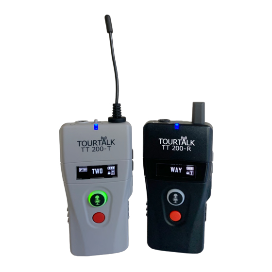
The TT 200-T transmitter is used by a group leader or assistant leader and is equipped with 3 communication modes for different applications. Tourtalk TT 200-ST stationary transmitter The TT 200-ST stationary transmitter is designed for long range and the professional conferencing market where the transmitter is to be mains powered. - Page 5 rechargeable batteries be used with a charger! The Tourtalk TT 200 is a full-duplex two-way communication system that allows group leaders and group members to fully communicate with each other during a tour. The system allows the tour group to talk to and be heard by each other;...
-
Page 6: Quick Start
The group leader (TT 200-T) can freely talk during the tour. Any one (1) of group members is able to ... - Page 7 G will show up on the screen to indicate correct connection with the transmitter. Note both transmitter and receiver need to be set at same channel to have correct communication mode (G, T or D) shown on receiver’s screen. Talkback by receiver Any one (1) group member (receiver) is allowed to talk back (FIFT) with a press of PTT button (○ ) if the group leader (transmitter) tunes its master/slave switch (○ ) to “s”. Power off To turn transmitter/receiver off, press and hold the power button (○ ○ ) till OFF shows up on the screen. Mode Teaching addition lecturer (TT‐200T, master), either assistant (TT‐200T, slave) ...
- Page 8 Power on a receiver and connect an earphone, headphone or headset Tune master/slave switch on transmitter correctly The lecturer (master transmitter) tunes its master/slave switch (○ ) to “m” whereas “s” is tuned by the assistant (slave transmitter). Note slave transmitter can work only when master transmitter exists. Assign your group channel Press both and buttons (○ ) simultaneously to unlock the channel when transmitter is on. Symbol disappears and press or button (○ ) to select another preferred channel. To confirm newly selected channel, press the power button (○ ) or leave the transmitter idle for 1 second to leave the setting automatically. Now, press and hold the power button (○ ) for 1 second to turn the receiver on. Press both and buttons (○ ) simultaneously to unlock the channel. ...
- Page 9 Power on a transmitter, connect a headset and change its communication mode Mode Discussing Any 2 discussion members (TT‐200T) are allowed to talk freely. Other listeners (TT‐200R) ...
- Page 10 transmitter and receiver need to be set at same channel to have correct communication mode (G, T or D) shown on receiver’s screen. When receivers are at communication mode “Discussing”, they do not have the talk right via the talk/mute button (○ ). Power off To turn transmitter/receiver off, press and hold the power button (○ ○ ) till OFF shows up on the screen. ...
-
Page 11: Interface
Interface Transmitter ○ 11. Headset jack socket ○ ○ ○ ○ ○ ○ The recommended 4-pin jack wiring is shown Please note. The Inbuilt microphone is muted when a headset ○... - Page 12 22. Earphone/Headphone/Headset jack socket Receiver ○ ○ ○ ○ ○ ○ ○ The recommended 4-pin jack wiring is shown Please note. The Inbuilt microphone is muted when a headset ...
-
Page 13: General Operation
General operation Power on ○ Press and hold the power button (○ ) for 1 second to turn transmitter/receiver on. Change communication mode on transmitter Press and hold both (○ ) and power (○ ) buttons simultaneously to turn transmitter on. Default mode T EACHING shows up. Press the or button (○ ) to change your preferred mode. Press the power button (○ ) to confirm (underline) the selection and leave the setting. Transmitter will then be turned on automatically. Detect communication mode on receiver Receiver will automatically detect the signal from transmitter when it is turned on. ( Steady ‐ Receiver : T , G or D will then show up on receiver’s screen for mode differentiation and indicating correct connection with the transmitter. Note both transmitter and receiver need to be set at same channel, then communication mode will show up automatically. To change your mode, simply turn receiver off and then re‐turn it on to acquire new signal from ... - Page 14 Please note. Listening to high volumes for long periods may damage your hearing . Adjust transmitter’s or receiver’s volume Transmitter Press or button (○ ) to adjust the headphone volume on transmitter. If channel-lock func-on is deac-vated (see paragraph of “Adjust default settings” on page 21), volume adjustment will be invalid and default volume will be fixed at level 5. ...
-
Page 15: Advanced Operation
Symbol indication No light Steady blue light Flashing blue light Flashing blue light for 10 seconds Flashing red light No light Steady green light Flashing red light Tourtalks proprietary software is available for developing bespoke ID numbers (max. of 4 digits) on the TT 200-T. - Page 16 for 5 seconds for auto‐confirmation. After selected channel is confirmed, signal indicator (○ ) starts to flash quickly and the talk/mute button (○ ) lights up in green. Transmitter is ready to send signal of channel unification. Now, turn receiver on and it will automatically be channel unified. New channel and correct Paired quantity Selected channel communication mode (G, T or D) will show up on its screen. Indication of successful or failed channel unification is shown above. Successful pairing Turn receiver off and then re‐turn it on if failed channel unification happens. To release the transmitter from channel unification, simply short press the talk/mute button (○ ) again. Communication mode (G, T or D) shown on receiver’s screen varies upon transmitter from which receiver acquires the signal. Failed pairing Pair and unify your group channel To complete following advanced functions, including roll‐call, calling/gathering alarm or out‐of‐range alarm, prior pairing for all transmitters/receivers in the group is a must. ...
- Page 17 for 5 seconds for auto‐confirmation. Channel number stops flashing. Signal indicator (○ ) starts to flash quickly which means the transmitter is ready for pairing. Now, turn receiver on. It will be paired and channel unified. Indication of successful or failed pairing is shown above. Turn receiver off and then re‐turn it on if failed pairing happens. Pairing quantity shown on transmitter will gradually increase until pairing is completed. Successful pairing To release the transmitter from group pairing, simply short press the call button (○ ) again to Failed pairing have it at standby screen or press the power button (○ ) to turn it off directly. Send pairing data to another transmitter ...
- Page 18 Actual group size Expected group size Roll‐call ...
- Page 19 Calling alarm Press hold call button (○ transmitter seconds when transmitter Calling symbol shows signal indicator (○ starts flash quickly which means transmitter sending signal calling alarm. ...
- Page 20 Out‐of‐range alarm Receivers will automatically start to vibrate and beep if they are out of transmitter’s range for 3 minutes. Out‐of‐range symbol ( ) shows up and PTT button (○ ) starts to flash quickly in red light. The alarm can only be released when receivers are within the operation range of the transmitter again or the alarm‐release button (○ ) on receivers is short pressed. Receivers will automatically be turned off if the alarm keeps on for 20 minutes. Out-of-range alarm can be deac1vated upon preference as advised in the paragraph of “Adjust default ...
- Page 21 Push to Bolt is Latching Push to Talk and Push to Mute are Momentary Adjust default settings Transmitter Press both (○ ) and power (○ ) buttons to turn transmitter on. ...
- Page 22 Back to default ○ Settings on both transmitter and receiver can be back to default at any time if , (○ ) and ○ power (○ ) buttons are pressed simultaneously when transmitter/receiver is off. Following are default settings for transmitter/receiver. Transmitter Channel: 01 Channel Lock: ON Talk: PTB Mic. Gain: 3 RF Power: Low Audio Priority: OFF Mode: T EACHING Receiver Channel: 01 Channel Lock: ON Auto Power‐Off: ON ...
-
Page 23: Troubleshooting
Troubleshooting NO DATA shows up on transmitter This screen might show up on transmitter and it means no prior pairing was completed. Please pair before requested operation is done. NOT APPLICABLE shows up on transmitter This screen might show up on transmitter and it means the function is not applicable. BUSY shows up on transmitter This screen might show up on transmitter and it means the talk right is occupied, please ask that occupied transmitter/receiver to release this talk right. DATA ERROR shows up on transmitter or receiver Transmitter Pairing data fails to acquire. Please turn the transmitter off and re‐turn it on again for successful acquirement of pairing data. Note same communication mode and channel need to be set on ○ both transmitters (if the communication mode is “Teaching”, the master/slave switch ( ) on both transmitters needs to be tuned at “m”). Receiver Pairing fails to complete. Please turn the receiver off and re‐turn it on again for successful pairing. ... - Page 24 If the receiver is set at T EACHING mode, make sure slave transmitter or any other receiver does not occupy the talk right. Receivers do not have the function of talkback if D ISCUSSING mode is set. Channel unification failed to proceed on Transmitter If the transmitter is set at T EACHING mode, make sure its master/slave switch (○ ) is tuned to be “m” not “s”. If the transmitter is set at D ISCUSSING mode, make sure any 2 transmitter does not occupy the talk right. ...
-
Page 25: Specifications
Transmitter TT 200-T Channels Country dependent (region dependent) Hi: 30 mW Low: 10 mW Specifications 4 ~ 6 hours @ 2,400 Up to 150 meters (line of sight) Frequency range 748 - 938 MHz (region dependent) Modulation 4 GFSK ... - Page 28 Systems 27 Mochdre Industrial Estate Newtown, Powys, UK Tel: +44 (1686) 628012 www.tourtalksystem.com...
Need help?
Do you have a question about the TT200 and is the answer not in the manual?
Questions and answers