Advertisement
PCB Components
U
M
SER
ANUAL
www.ledtreiber.de
Contens ...................................................................................................................................................... 1
Overview And Features .............................................................................................................................. 2
Connections Layout / Pwm Input ............................................................................................................... 3
Technical Data / Examples Of Connections ............................................................................................. 4-5
Change Of Measurement Resistor / Increase Output Power To 3A ............................................................. 6
© PCB Components – English Manual v1.3
Advertisement
Table of Contents

Summary of Contents for PCB Components Micro KSQ Series
- Page 1 Contens ..............................1 Overview and Features ..........................2 Connections layout / PWM input ....................... 3 Technical data / Examples of connections ..................... 4-5 Change of measurement resistor / Increase output power to 3A ............. 6 © PCB Components – English Manual v1.3...
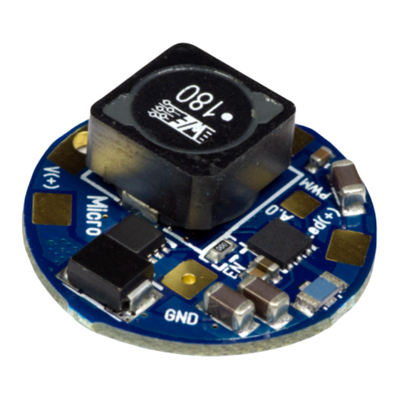
- Page 2 Overview and Features Thank you for purchasing this product. The Micro KSQ series consists of two different versions: one for the 1.5 amp version which is based on LEDs at higher currents than the typical 1A such as the Cree XPG 2 and the other the 2.8 ampere version which is a counterpart to our Black Power Series and operates...
- Page 3 The PWM input can be fed with our μ-Dim, LedStripe, NanoDim dimmer or a separate signal and thus regulate the brightness of the Micro. Please check the guide in one manual of the above dimmer. Micro • © PCB Components English Manual v1.3...
- Page 4 50/50%, but by the fluctuations of a typical diode, the LED current is distributed in such two parallel lines is not exactly 50/50%. If in a parallel connection one strand lose, the current is distributed to the remaining (n) Led strands. Micro • © PCB Components English Manual v1.3...
- Page 5 Increase the output current to 3A (Micro 2800) or 1.7A (Micro 1500) In order to increase the current e.g. for the Cree XM-L to 3 amps, the small bridge (circled in red) needs to be closed. Micro • © PCB Components English Manual v1.3...
- Page 6 Examples of connections Efficiency: Micro • © PCB Components English Manual v1.3...
Need help?
Do you have a question about the Micro KSQ Series and is the answer not in the manual?
Questions and answers