Advertisement
THIS INSTRUCTION BOOKLET CONTAINS IMPORTANT SAFETY INFORMATION. PLEASE READ AND KEEP FOR FUTURE REFERENCE.
Please give us a chance to make it right and do better!
Contact our friendly customer service department for help first.
Replacements for missing or damaged parts will be shipped ASAP!
Follow Costway
Visit us: www.costway.com
USER'S MANUAL
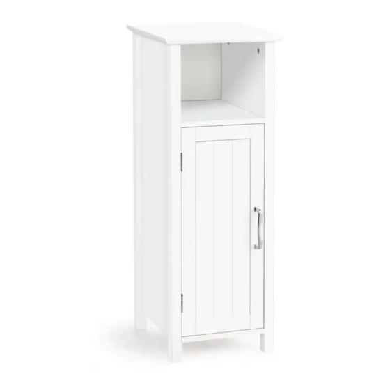
Storage Cabinet
HW61186
FLOOR AREA
2MX2M
ASSEMBLED BY 1 ADULT
EN
DE
FR
ES
IT
Advertisement
Table of Contents

Subscribe to Our Youtube Channel
Related Manuals for Costway HW61186


Summary of Contents for Costway HW61186
- Page 1 Please give us a chance to make it right and do better! FLOOR AREA 2MX2M Contact our friendly customer service department for help first. Replacements for missing or damaged parts will be shipped ASAP! Follow Costway Visit us: www.costway.com ASSEMBLED BY 1 ADULT...
- Page 2 Contact Us! Do NOT return this item. Contact our friendly customer service department for help first. product Before You Start Read each step carefully before starting. It is very important to ensure each step followed in correct order, otherwise assembly difficulties may occur. Most of board parts are labeled or stamped on the raw edges.
- Page 3 please contact us in time. 35mm Male Camlock x 12 Female Camlock x 12 30mm Wooden Dowel x 12 Top Panel x 1 Left Side Panel x 1 Right Side Panel x 1 (30(w)cmx30(d)cm) (78.5(w)cmx28.4 (d)cm) (78.5(w)cmx28.4(d)cm) Magnetic Catch x 1 Catch Plate x 1 Hinge x 2 10mm Screw x 9 Handle x 1...
- Page 4 Inserting Male Camlocks 1. Insert 12 x Male Camlocks A into Panels 1 and 3 as shown. 2. Connect Magnetic Catch D to Right Side Panel 3 as shown using 2 x Screw F. The unit is floor standing, but it is recommended that the unit is secured to the wall.
- Page 5 1. Insert 4 x Dowels C into 1. Insert 4 x Shelf the top edge of Side Panels Supports L into internal and 3 as shown holes in Side Panels 2 and 3. 2. Locate Top Panel 1 into positon as shown. 2.
- Page 6 1. Connect Handle I to the Door using 2 x Screws 2. Connect the Door to the unit by attaching the hinges to Side Panel 2 as shown using 2 x Screw H per Hinge The unit is floor standing, but it is recommended that the unit is secured to the wall.
Need help?
Do you have a question about the HW61186 and is the answer not in the manual?
Questions and answers