Table of Contents
Advertisement
Quick Links
Rev 4
August 2014
A.R. Wilfley and Sons, Inc.
®
EMW
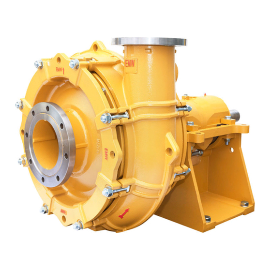
SLURRY PUMP - METAL
Installation, Operation, Maintenance and Storage Manual
VISIT US AT
.WILFLEY.
WWW
COM
7350 E. Progress Place, Englewood, CO 80111 USA • Toll Free: 1-800-525-9930 • Phone: +1 (303) 779-1777 • Fax: +1 (303) 779-1277
www.wilfley.com • pumps@wilfley.com
Advertisement
Table of Contents

Related Manuals for Wilfley EMW Series


Summary of Contents for Wilfley EMW Series
- Page 1 Rev 4 August 2014 A.R. Wilfley and Sons, Inc. ® SLURRY PUMP - METAL Installation, Operation, Maintenance and Storage Manual VISIT US AT .WILFLEY. 7350 E. Progress Place, Englewood, CO 80111 USA • Toll Free: 1-800-525-9930 • Phone: +1 (303) 779-1777 • Fax: +1 (303) 779-1277...
-
Page 2: Table Of Contents
Rev 4 August 2014 A.R. Wilfley and Sons, Inc. TABLE OF CONTENTS 7.3 Wear Adjustment ........... 11 Forward ................2 7.4 General Servicing Attributes ........11 1.0 Introduction ..............3 7.5 Impeller Replacement ..........11 2.0 Safety Considerations ..........3 7.6 Designation ............ -
Page 3: Forward
A.R. Wilfley & Sons, Inc. (ARW) shall not be liable for damage or delays caused by a failure to observe the instructions for installation, operation, maintenance, and storage contained in this manual. -
Page 4: Introduction
If detailed 10. Do not rely on the factory’s alignment of the questions or problems arise, contact the Wilfley pump and the drive system. Alignment may Sales Office, Distributors, or Representatives. -
Page 5: Safety Tips
Rev 4 August 2014 A.R. Wilfley and Sons, Inc. • Every pump has the potential to be dangerous due Wear steel toe shoes for protection when to the following factors: handling parts, heavy tools, etc. • • Parts are rotating at high speeds. -
Page 6: Unauthorized Modification And Manufacture Of Spare Parts
Rev 4 August 2014 A.R. Wilfley and Sons, Inc. • Never apply heat to remove impeller. WARNING • Observe all cautions and warnings highlighted in pump instruction manual. Care should be taken to ensure all lifting lines are properly installed to prevent a load shift. A 2.2 Unauthorized Modification and... -
Page 7: Storage Requirements
Rev 4 August 2014 A.R. Wilfley and Sons, Inc. protective lubrication between the balls and 3.3 Storage Requirements raceways and lead to metal to metal cyclical impacting. This is sometimes referred to as If the pump is inoperative for an extended of time, false brinneling. -
Page 8: Foundation
Rev 4 August 2014 A.R. Wilfley and Sons, Inc. 2. Place the pump in a location that allows easy WARNING access to the unit for inspection during operation and maintenance, which involve removal and disassembly. A rapidly closing discharge valve can cause a 4.3 Foundation... -
Page 9: Piping Note
Rev 4 August 2014 A.R. Wilfley and Sons, Inc. 4.9 Piping Note POSSIBLE RECOMMENDED PROBLEM CAUSE REMEDY Refer to the Hydraulic Institute Standards for centrifugal pumps for additional piping information. Loosen pump hold down bolts and slide Driver feet 4.10 Installation and Alignment pump and driver until bolt bound. -
Page 10: Commissioning, Start-Up And Shutdown Instructions
Rev 4 August 2014 A.R. Wilfley and Sons, Inc. 6.0 Commissioning, Start-Up and WARNING Shutdown Instructions 6.1 Commissioning The electrical connections must be disconnected and locked out. Make sure the pump cannot be switched on accidentally. Use proper eye and face protection when... -
Page 11: Visual Inspections
Rev 4 August 2014 A.R. Wilfley and Sons, Inc. 7.1.2 Visual Inspections 7.2.4 Oil Lubrication Periodic visual inspection should be made of the Viscosity grade recommendations based on pump and its installation. temperature are listed in the following table. This inspection should include the following:... -
Page 12: Wear Adjustment
Rev 4 August 2014 A.R. Wilfley and Sons, Inc. 7.3 Wear Adjustment 7.5 Impeller Replacement Note: Any work on non-pump equipment shall be CAUTION governed by the specifications and regulations of the manufacturer. Ensure that lockout tags are in place. -
Page 13: Designation
Rev 4 August 2014 A.R. Wilfley and Sons, Inc. open to allow inspection of or removal of the impeller 7.6 Designation from an installed pump. The casing can be rotated in 45 degree increments (90 degrees for the size 75... -
Page 14: Packing Seal
But, before specifying a seal consult with a Wilfley Representative as engineering approval is In general, parts should be cleaned to remove such required for such applications. -
Page 15: Specialized Tools For Assembly And Disassembly
Rev 4 August 2014 A.R. Wilfley and Sons, Inc. 9.1.3 Shaft Handling Tool A 12 mm tapped hole in the end of the shaft CAUTION provides a location for a hoisting attachment such as an eyebolt to assist with vertical positioning of the shaft for insertion into or removal from a bearing cartridge. -
Page 16: General Pump Assembly Sequence
Rev 4 August 2014 A.R. Wilfley and Sons, Inc. 10.0 General Pump Assembly Sequence 10.1 Power End Assembly Step 1 – Shaft assembly. The thrust bearings (16) are two taper roller bearings mounted to the shaft in a face- to-face arrangement. The radial bearing (18) is a spherical roller bearing. The thrust bearings are a matched pair and cannot be assembled by mixing and matching pairs. - Page 17 Rev 4 August 2014 A.R. Wilfley and Sons, Inc. Step 2 – Bearing Cartridge Assembly. To install the shaft assembly from Step 1 into the bearing cartridge (99), the shaft should be vertically lowered, radial bearing or keyed side first, into the bearing cartridge. If unsure which side of the bearing cartridge is which, the side that has a lip in the bore is the thrust bearing side, and that side will be the side the shaft is lowered into.
- Page 18 Rev 4 August 2014 A.R. Wilfley and Sons, Inc. Step 2 – Lowering the shaft into the bearing cartridge Press fit the bearing isolaters (47) and (49) into the bearing caps (35) and (37) respectively. Next install the o- rings (35B) into the thrust bearing cap (35), and (37A) into the radial bearing cap (37). If the bearings are grease lubricated, the area directly outboard from the bearings should be packed with grease prior to assembling the bearing caps.
- Page 19 Rev 4 August 2014 A.R. Wilfley and Sons, Inc. Step 3 – Pedestal Assembly. Install the clearance adjustment bolt (149), nuts (149B), and washers (149C) into the pedestal (53). At this point it is recommended to bolt the pedestal to a rigid base or structure to prevent it from tipping forward when the wet end of the pump is assembled.
- Page 20 Rev 4 August 2014 A.R. Wilfley and Sons, Inc. Step 4 – Power End Assembly. To complete the assembly of the power end, lower the bearing cartridge assembly from Step 2 onto the pedestal assembly from Step 3, making sure the threaded side of the shaft is on the bracket side.
- Page 21 Rev 4 August 2014 A.R. Wilfley and Sons, Inc. Step 5 – Shaft sleeve assembly (Pump size 150 (6x4) and smaller). Install the o-ring (119B) into the ID groove in the shaft sleeve (14). Slide the shaft sleeve, chamfered end first, onto the front end of the shaft (6).
- Page 22 Rev 4 August 2014 A.R. Wilfley and Sons, Inc. Step 5 - Release Collar Sleeve Assembly (Pump size 200 (8x6) and larger) – Install the o-ring (36A) in the ID groove in the release collar sleeve (36B). Slide the release collar sleeve, chamfered end first, onto the shaft (6).
- Page 23 Rev 4 August 2014 A.R. Wilfley and Sons, Inc. Shaft Sleeve / Release Collar Installation (Pumps Size 200 (8x6) and Larger) 7350 E. Progress Place, Englewood, CO 80111 USA • Toll Free: 1-800-525-9930 • Phone: +1 (303) 779-1777 • Fax: +1 (303) 779-1277 www.wilfley.com •...
-
Page 24: Wet End Assembly
Rev 4 August 2014 A.R. Wilfley and Sons, Inc. 10.2 Wet End Assembly Step 6 – 7: Seal and Wet End Assembly. There are a variety of seals available for the EMW pump. Please turn to the appropriate page in table 6-1 based on which seal is installed in your pump. - Page 25 Rev 4 August 2014 A.R. Wilfley and Sons, Inc. To prevent a packing seal failure the packing in all expeller sealed pumps must be lubricated during pump operation. An o-ring (71C) seals the case and expeller cover joint and another o-ring (83C) seals the expeller cover and the stuffing box joint as seen in the figures below.
- Page 26 Rev 4 August 2014 A.R. Wilfley and Sons, Inc. The flush configuration (spacer ring, lantern ring, and three rings of packing) directs the majority of the coolant towards the seal chamber, pushing solids away from the packing using more flush water.
- Page 27 Rev 4 August 2014 A.R. Wilfley and Sons, Inc. Step 7 – Case Assembly (Expeller Seal). At this point, if the pump assembly is not bolted down, it must be attached to a structure or workbench before proceeding. The pump will tip forward when the case is assembled onto the pump.
- Page 28 Rev 4 August 2014 A.R. Wilfley and Sons, Inc. Step 8 (Expeller Seal) – Install the expeller o-ring (4A) into the expeller and thread the impeller (2) onto the shaft. Tighten the impeller. Step 8 – Impeller Installation The impeller used with an expeller seal has long pump out vanes on the backside that extend almost all the way down to the hub.
-
Page 29: Packing
Rev 4 August 2014 A.R. Wilfley and Sons, Inc. 10.2.2 Packing Step 6-1 – Packing Seal Assembly. The packing seal creates a simple static and dynamic seal. Step 6-1 - Packing Seal Components (Weep Configuration Shown) The packing seal consists of a stuffing box (83X) four rings of packing (13), a lantern ring (29), a spacer ring (63), a gland plate (17), a gland ring (17C), two gland studs (17A) and two gland nuts (17B). - Page 30 Rev 4 August 2014 A.R. Wilfley and Sons, Inc. Packing Seal (Weep Configuration) The weep configuration (spacer ring, packing ring, lantern ring, and three rings of packing) directs a lesser amount of coolant towards the seal chamber than a flush configuration and uses less flush water.
- Page 31 Rev 4 August 2014 A.R. Wilfley and Sons, Inc. Step 6-2 – Wet end assembly – Packing Seal. Install the shaft o-ring (119B) into the shaft sleeve (14) and insert the shaft sleeve onto the shaft (6) butting it up against the release collar (36). Take the stuffing box assembly (83P) and slide it onto the shaft sleeve (14).
- Page 32 Rev 4 August 2014 A.R. Wilfley and Sons, Inc. Step 7 – Case Assembly - Packing Seal. At this point, if the pump assembly is not bolted down, it must be attached to a structure or workbench before proceeding. The pump will tip forward when the case is assembled onto the pump.
- Page 33 Rev 4 August 2014 A.R. Wilfley and Sons, Inc. Step 8 - Packing Seal – If you have not already done so, install the shaft sleeve o-ring (119A) into the shaft sleeve (14) and slide the spacer sleeve (34) onto the shaft (6). Install the spacer sleeve o-ring (34A) into the spacer sleeve (34) and thread the impeller (2) onto the shaft.
-
Page 34: Mechanical Seal
Rev 4 August 2014 A.R. Wilfley and Sons, Inc. 10.2.3 Mechanical Seal Step 6 - Mechanical Seals. The seal chamber space available for mounting a mechanical seal (89S) is sufficiently large to accommodate most OEM mechanical seal products. The stuffing box extension (83E) in a mechanical seal pump is the same one used with a packing seal pump. - Page 35 Rev 4 August 2014 A.R. Wilfley and Sons, Inc. Step 6 - Mechanical Seals – Install the seal assembly (89) into the stuffing box (83). The shaft sleeve (14) and o-ring (119B) can be installed on the shaft before installing the seal assembly or it can be inserted into the seal assembly and slid onto the shaft when the stuffing box is assembled to the bracket.
- Page 36 Rev 4 August 2014 A.R. Wilfley and Sons, Inc. Step 7 – Case Assembly - Mechanical Seal – Install the stuffing box extension o-ring (83G) into the stuffing box extension and assemble the case with hardware (259, 259A, 259C) to the bracket, torque nuts (259C) to 80 N-m (60 Lb-Ft).
- Page 37 Rev 4 August 2014 A.R. Wilfley and Sons, Inc. Cartridge Style Mechanical Seal Step 8 - Cartridge Style Mechanical Seal – If you have not already done so, install the shaft sleeve o-ring (119A) into the shaft sleeve (14) and slide the spacer sleeve (34) onto the shaft (6). Install the spacer sleeve o- ring (34A) into the spacer sleeve (34) and thread the impeller (2) onto the shaft.
- Page 38 Rev 4 August 2014 A.R. Wilfley and Sons, Inc. Semi-Cartridge Style Mechanical Seal Step 8 - Semi-Cartridge Style Mechanical Seal. If a semi-cartridge seal of the type shown in Assembly Step 6 is used install the o-ring (119A) into the shaft sleeve (14) and slide the rotary seal face onto the shaft. Install the o-ring supplied with the mechanical seal into the mechanical seal rotary face and thread the impeller (2) onto the shaft.
-
Page 39: Suction Cover Assembly
Rev 4 August 2014 A.R. Wilfley and Sons, Inc. 10.5 Suction Cover Assembly 10.5.1 Pumps Size 150 (6x4) and Smaller Step 9 – Suction Cover Assembly - (Pumps Size 150 and Smaller) – Slide the suction cover o-ring (73) onto the suction cover (9) and assemble it to the case (1) with hardware (259, 259A, 259C). -
Page 40: Pumps Size 200 (8X6) And Larger
Rev 4 August 2014 A.R. Wilfley and Sons, Inc. 10.5.2 Pumps Size 200 (8x6) and Larger Step 9-1 – Suction Cover Assembly - (Pumps Size 200 and Larger, Expeller Seal) – Install the bushing o-ring (10A) and hardware (10B, 10C) into the case bushing (10). Slide the just assembled case bushing with hardware onto the adjustable suction cover (9). -
Page 41: Flange Assembly
Rev 4 August 2014 A.R. Wilfley and Sons, Inc. 10.6 Flange Assembly Step 11 (Flange Assembly) – Slip fit the suction flange (9A) over the neck on the suction cover (9) and the discharge flange (251) over the neck on the case (1). Pry open the suction flange split ring (9B) and slide it over the neck on suction cover to rest on the cone taper. -
Page 42: Seal Guard Assembly
Rev 4 August 2014 A.R. Wilfley and Sons, Inc. 10.7 Seal Guard Assembly Step 12 (Guard Assembly) – Assemble the upper and lower seal chamber guards (132) and (133) and hardware (132A) and (132B) to the pedestal (53). Step 12 – Seal Guard Assembly 7350 E. -
Page 43: Setting Clearances
Rev 4 August 2014 A.R. Wilfley and Sons, Inc. 10.8 Setting Clearances 10.8.1 Pumps Size 150 (6x4) and Smaller Step 13 – Clearance Setting Step 13 (Size 150 (6x4) and Smaller) Running Clearance Setting – On pumps size 150 (6x4) and smaller, the impeller running clearance is controlled by adjusting the bearing cartridge position in the pedestal. -
Page 44: Pumps Size 200 (8X6) And Larger
Rev 4 August 2014 A.R. Wilfley and Sons, Inc. 10.8.2 Pumps Size 200 (8x6) and Larger Step 13 – Clearance Setting Step 13 (Size 200 (8x6) and Larger) Running Clearance Setting – On pumps size 200M (8x6) and larger, two adjustments are available which allows the user to control both the impeller and expeller running clearance. -
Page 45: General Specifications
Rev 4 August 2014 A.R. Wilfley and Sons, Inc. 11.0 General Specifications 11.1 Forces and Moments Forces and moments only apply to static pipelines. The values are applicable when pump is installed on a grouted and even foundation. Note: Discharge nozzle coordinate system always moves with nozzle angle, Fz always moves in direction of flow. -
Page 46: Noise Characteristics
Rev 4 August 2014 A.R. Wilfley and Sons, Inc. 11.2 Noise Characteristics When running the pump within the normal limits of operation and on clear liquids, the sound pressure level for the pump alone does not exceed 80 dBa. Coarse solids, froth, or cavitation conditions can increase noise levels. -
Page 47: Troubleshooting
Rev 4 August 2014 A.R. Wilfley and Sons, Inc. 12.0 Troubleshooting SYMPTOMS POSSIBLE CAUSES Pump not primed Pump or suction pipe not completely filled with liquid Suction lift too high Insufficient NPSH Air pocket in suction line Air leaks in suction line... - Page 48 Rev 4 August 2014 A.R. Wilfley and Sons, Inc. Appendix 1 Bearing Operating Temperature Range 63°C to 76°C (145°F to 170°F) Lubrication Amount Lubrication Interval Based On Pump Run Time Pump Thrust Radial 8 hrs/day 16 hrs/day 24 hrs/day 50 (2x2) 7 g (0.2 oz)
Need help?
Do you have a question about the EMW Series and is the answer not in the manual?
Questions and answers