Table of Contents
Advertisement
Quick Links
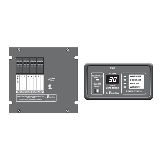
30A SMART ENERGY MANAGEMENT SYSTEM
30 Amp EMS Distribution Panel
P/N 00-00912-000
The 30A SMART EMS is a centralized power switching, fusing, and distribution center. Power from the 120
volt power source is fed into the box. The potential of lethal electrical shock is present in this box. Inadvertent
shorts at this box could result in damage and/or injury. All servicing of this box should be done
qualified Service Technician.
Diagnostic tools required: Low current Test Light, Accurate Voltmeter (digital readout preferred), Clamp-on AC
ammeter.
PRODUCT DESCRIPTION
The
30A SMART EMS
System, intended for use in recreational vehicles. It is housed in a sheet metal enclosure with removable front panel.
It provides circuit protection for all the 120 VAC loads in the RV and a system of energy management to minimize the
over-loading and tripping of circuit breakers.
Circuit Breakers
The
30A SMART EMS
breakers must be a 30 Amp unit that acts as a main input protection for the remainder of the branch breakers (up
to 7).
Energy Management
The
30A SMART EMS
current draw to less than 30 Amps. These appliances may be any type load, but are typically heavier loads,
those whose use can be "postponed" until a time when current is available for their use.
Intellitec
www.intellitec.com
INSTALLATION & SERVICE MANUAL
A
TM
TM
is a completely self-contained 120 volt Power Distribution and Energy Management
TM
offers slots for four single or dual, standard 120 volt circuit breakers. One of these
TM
offers control of up to four, 120 volt operated appliances to help keep the total 120 volt
MODEL 500A
CAUTION
30 Amp EMS Display Panel
P/N 00-00903-030 (Black)
P/N 53-00912-000 Rev. D 080919
TM
only
by a
1485 Jacobs Rd.
Deland, FL 32724
386.738.7307
Advertisement
Table of Contents

Subscribe to Our Youtube Channel
Summary of Contents for Intellitec 500A
- Page 1 30A SMART ENERGY MANAGEMENT SYSTEM MODEL 500A INSTALLATION & SERVICE MANUAL 30 Amp EMS Display Panel P/N 00-00903-030 (Black) 30 Amp EMS Distribution Panel P/N 00-00912-000 CAUTION The 30A SMART EMS is a centralized power switching, fusing, and distribution center. Power from the 120 volt power source is fed into the box.
-
Page 2: Circuit Protection
30A SMART ENERGY MANAGEMENT SYSTEM MODEL 500A INSTALLATION & SERVICE MANUAL System Communications 30 Amp Smart EMS Control Module utilizes Intellitec’s RV Multiplex/PMC (Programmable Multiplex Control) System as the communications link between the Display Panel and the Distribution Panel. As an additional diagnostic feature, the system includes two Communications Status LED’s on the Control Module. -
Page 3: Operation
30A SMART ENERGY MANAGEMENT SYSTEM MODEL 500A INSTALLATION & SERVICE MANUAL CONTROLLED LOADS The system offers control of up to four 120 VAC powered loads. Loads that are to be controlled are connected to one of the relay circuits of the . -
Page 4: Installation
30A SMART ENERGY MANAGEMENT SYSTEM MODEL 500A INSTALLATION & SERVICE MANUAL The “Service Select” button allows the service type to be set to either 30 Amps or 20 Amps, to match the incoming service. If the pictured adaptor is used on the incoming service, press the “Service Select”... - Page 5 30A SMART ENERGY MANAGEMENT SYSTEM MODEL 500A INSTALLATION & SERVICE MANUAL The dip-switches position 1 thru 5 are all preset to “ON” at the factory. Changing the setting of S1-1, S1-2, or S1-3 will alter the order of shedding to suit the particular need of the installation. The tables below will assist in determining the proper settings for S1-1 thru S1-3.
- Page 6 30A SMART ENERGY MANAGEMENT SYSTEM MODEL 500A INSTALLATION & SERVICE MANUAL J4 - LOW VOLTAGE RELAY CONNECTOR J5 - DISPLAY CONNECTOR 5A 32V FUSE J7 - RELAY 3 J2 - +12V POWER CONNECTOR J3 - TO CURRENT TRANSDUCER RELAY 2...
- Page 7 30A SMART ENERGY MANAGEMENT SYSTEM MODEL 500A INSTALLATION & SERVICE MANUAL PLACEMENT The EMS should be installed in a convenient location where it can get air circulation to keep it from over heating. There should be a minimum of 7" of depth behind the mounting surface to provide enough room for the box and wiring.
- Page 8 30A SMART ENERGY MANAGEMENT SYSTEM MODEL 500A INSTALLATION & SERVICE MANUAL The 12 VDC voltage connections are made through J2, a 3 pin Mate-N-Lok connector on the low voltage side of the control module. The +12 volts should be supplied from a source fused at 3 Amps minimum and capable of delivering up to 1 Amp of AVERAGE current.
- Page 9 30A SMART ENERGY MANAGEMENT SYSTEM MODEL 500A INSTALLATION & SERVICE MANUAL Finally, on the Control Module, there is a small 2 pin plug labeled J1 which is only used for the High Pot Test on the system. When the two pins are shorted together, the EMS will operate without the presence of 120 VAC.
-
Page 10: Performance Test
30A SMART ENERGY MANAGEMENT SYSTEM MODEL 500A INSTALLATION & SERVICE MANUAL PERFORMANCE TEST The system is now ready for testing. Hi-POT TEST At the installers preference, to assure there are no potential shorts, a Hi-Pot test can be performed on the installation. - Page 11 30A SMART ENERGY MANAGEMENT SYSTEM MODEL 500A INSTALLATION & SERVICE MANUAL FUSES - 5 Amp ATO type, for EMS Control Module circuitry only. DO NOT replace with a fuse of higher rating . This could result in severe damage to the circuitry or create a possible fire hazard.
-
Page 12: Troubleshooting
30A SMART ENERGY MANAGEMENT SYSTEM MODEL 500A INSTALLATION & SERVICE MANUAL J6 = 5 Position Terminal Block Term Function From Circuit Breaker for Relay 2 Output of Relay 2 From Circuit Breaker for Relay 1 Output of Relay 1 Neutral... - Page 13 30A SMART ENERGY MANAGEMENT SYSTEM MODEL 500A INSTALLATION & SERVICE MANUAL Trouble Shooting (Continued) Check 120 volt circuit breakers in EMS 1. Reset circuit breakers if necessary. 2. Check for presence of voltage at branch circuit breakers with voltmeter. 3. Check for presence of voltage at EMS terminals with voltmeter.
- Page 14 30A SMART ENERGY MANAGEMENT SYSTEM MODEL 500A INSTALLATION & SERVICE MANUAL 1485 Jacobs Rd. Intellitec Deland, FL 32724 386.738.7307 www.intellitec.com P/N 53-00912-000 Rev. D 080919...
- Page 15 30A SMART ENERGY MANAGEMENT SYSTEM MODEL 500A INSTALLATION & SERVICE MANUAL 1485 Jacobs Rd. Intellitec Deland, FL 32724 386.738.7307 www.intellitec.com P/N 53-00912-000 Rev. D 080919...
- Page 16 30A SMART ENERGY MANAGEMENT SYSTEM MODEL 500A INSTALLATION & SERVICE MANUAL 1485 Jacobs Rd. Intellitec Deland, FL 32724 386.738.7307 www.intellitec.com P/N 53-00912-000 Rev. D 080919...
Need help?
Do you have a question about the 500A and is the answer not in the manual?
Questions and answers