Advertisement
Quick Links
m
i
c
r
o
m
i
c
r
o
I
n
s
I
n
s
E
a
s
E
a
s
May 2010, Rev 1
B
r
u
t
e
B
r
u
t
e
t
r
u
c
t
i
o
t
r
u
c
t
i
o
t
e
r
n
V
o
l
t
a
g
e
t
e
r
n
V
o
l
t
a
g
e
− 1 −
microBrute Modulator
M
o
d
u
M
o
d
u
n
M
a
n
u
n
M
a
n
R
e
s
e
a
r
c
h
,
L
R
e
s
e
a
r
c
h
,
L
© 2010 Eastern Voltage Research, LLC
microBrute Modulator Instruction Manual
l
a
t
o
r
l
a
t
o
r
a
l
u
a
l
L
C
L
C
Advertisement

Summary of Contents for eastern microBrute
- Page 1 Modulator − 1 − May 2010, Rev 1 © 2010 Eastern Voltage Research, LLC microBrute Modulator Instruction Manual...
-
Page 2: Circuit Description
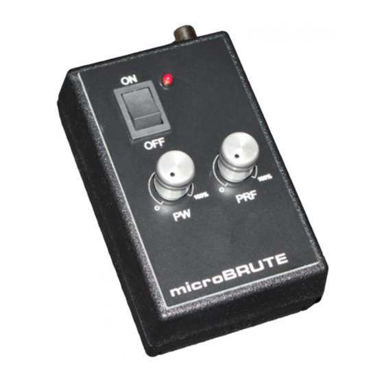
(PRF) of the modulation (pulsing). The microBrute Modulator can also be modified by the user to utilize different ranges of pulsewidths and PRFs to suit most any SSTC or DRSSTC system. -
Page 3: Kit Building Tips
You can then remove the masking tape, apply a small amount of solder on the top to complete the joint. − 3 − May 2010, Rev 1 © 2010 Eastern Voltage Research, LLC microBrute Modulator Instruction Manual... - Page 4 9V Battery Connector, BAT1 Panel Switch, ON-OFF, SW1 Knob, 1/8” Shaft Front Panel Plate Misc. Hardware Misc. Hook-up Wire REQUIRED, NOT SUPPLIED 9V Battery − 4 − May 2010, Rev 1 © 2010 Eastern Voltage Research, LLC microBrute Modulator Instruction Manual...
- Page 5 Modulator microBrute Modulator Component Layout Diagram − 5 − May 2010, Rev 1 © 2010 Eastern Voltage Research, LLC microBrute Modulator Instruction Manual...
- Page 6 6. Install CR1, 1N4002 diode. The cathode band on the diode must match that shown on the silkscreen. 7. Install C1, 0.1uF capacitor (marking BC104) − 6 − May 2010, Rev 1 © 2010 Eastern Voltage Research, LLC microBrute Modulator Instruction Manual...
- Page 7 − 7 − May 2010, Rev 1 © 2010 Eastern Voltage Research, LLC microBrute Modulator Instruction Manual...
- Page 8 Apply lots of pressure over all areas of the control plate to ensure good contact with the enclosure surface. − 8 − May 2010, Rev 1 © 2010 Eastern Voltage Research, LLC microBrute Modulator Instruction Manual...
- Page 9 29. Connect J1 to the PC board as shown in the figure below. The center lead of the connector should connect to the pad marked “+” on the PC board. − 9 − May 2010, Rev 1 © 2010 Eastern Voltage Research, LLC microBrute Modulator Instruction Manual...
- Page 10 Modulator − 10 − May 2010, Rev 1 © 2010 Eastern Voltage Research, LLC microBrute Modulator Instruction Manual...
-
Page 11: Set-Up And Testing
Modulator Congratulations! You have just completed your microBrute Modulator kit. Please take a few moments to look over the board and ensure that all the components are installed properly with the correct orientation. Since some of the parts may be unfamiliar to you, you may want to be extra sure that they have been inserted correctly. -
Page 12: Troubleshooting
SOLUTION: LED may be installed backwards. Conclusion We sincerely hope that you have enjoyed the construction of this Eastern Voltage Research Kit. As always, we have tried to write this instruction manual in the easiest, most “user friendly” format that is possible. As our customers, we value your opinions, comments, and additions that you would like to see in future publications. - Page 13 Legal Status of Products It is the responsibility of the Buyer (not Eastern Voltage Research, LLC) to ascertain and obey all applicable local, state, and federal laws in regard to the possession and the use of any item or kit that is offered for sale. Consult your attorney regarding local, state, and federal laws prior to ordering.
- Page 14 However, on rare occasions, components which are defective may be shipped and included in your kit. All of our kit parts carry the Eastern Voltage Research, LLC Warranty that they are free from defects for a full ninety (90) days from the date purchase with the exception of power semiconductors (see below).
- Page 15 Components Return Policy Individually purchased components may not be returned for any reason. If you do not agree with this policy, please do not order. − 15 − May 2010, Rev 1 © 2010 Eastern Voltage Research, LLC microBrute Modulator Instruction Manual...
Need help?
Do you have a question about the microBrute and is the answer not in the manual?
Questions and answers