Advertisement
http://waterheatertimer.org/Din-rail-timers-and-manuals.html
Any Electronics Co.,Ltd.
+35℃ in 24h.
3.2 Altitude: no more than 2,000m.
3.3 Humidity: the relative air humidity of the installation site shall be no more than 50% when the
maximum temperature is +40℃, while it can be higher under lower temperature. Special measures
shall be taken for the condensation occasionally formed due to temperature change.
3.4 Pollution level: 3.
3.5 In the medium with no explosion hazard and no gas that is enough to corrode metal and
destroy the insulation and the place shall not have severe conductive dust.
3.6 In the place where is provided with anti-snow and anti-rain equipment but not be full of water
steam.
3.7 In the place without significant shake, shock and vibration.
3.8 Installation class: II.
3.9 Transport and Storage Conditions: -25℃ to +55℃.
3.10 Power voltage change scope: 85%~110% rated voltage.
3.11 Protection grade: IP20.
4 Main Technical Parameters
4.1 Rated control power voltage: AC (50Hz): 220V.
4.2 Conventional thermal current: (Ith)16A.
4.3 Category of the auxiliary circuit: AC-15.
4.4 Rated working current (Ie): AC-15 220V 3A.
4.5 Timing error: ≤1s/d.
4.6 Time control scope: 1sec~168h.
4.7 Mechanical life: ≥30,000 times.
4.8 Electric endurance: ≥10,000 times.
4.9 Installation method: Device installed, guide tracked.
4.10 Anti-interference tolerance sees Table 1.
https://www.timer-switch.com/
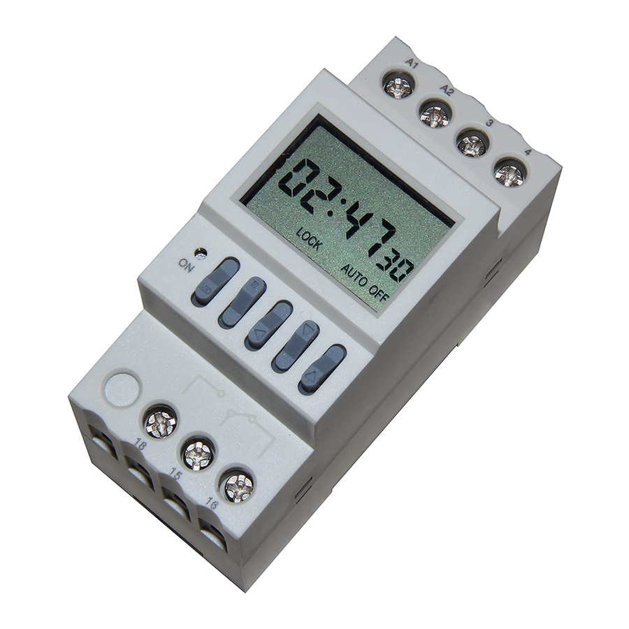
ATP1006-2 Time Switch
(The time switch timing can be set second.)
1. Function and Scope
ATP1006-2 time switch (hereinafter referred
to as "time switch") is applicable for
regularly controlling switch-on and off of
street lamps, advertising light boxes and
other equipments in automatic control
circuit with AC frequency of 50Hz, rated
control power voltage of 220V at most and
rated working current of 3A at most.
2. Model and Its Meaning: ATP1006-2
3.
Normal
Operating
Installation Condition
3.1 Ambient air humidity: -25℃~+40℃,
and the average temperature is no more than
Condition
and
Advertisement
Table of Contents

Summary of Contents for any ATP1006-2
- Page 1 AC frequency of 50Hz, rated control power voltage of 220V at most and rated working current of 3A at most. 2. Model and Its Meaning: ATP1006-2 Normal Operating Condition Installation Condition 3.1 Ambient air humidity: -25℃~+40℃,...
- Page 2 5.1 Outside dimension and installation dimension see Figure 1. a) ATP1006-2 outside dimension b)ATP1006-2 installation dimension Figure 1 Outside dimensions and installation dimensions of ATP1006-2 5.2 Wiring method 5.2.1 Direct control method Power of the controlled appliance is supplied in single-phase, of which the working current is no more than the rated value of this switch.
- Page 3 Figure 2 Direct single-phase controlled wiring diagram Figure 3 Single-phase expansion controlled wiring diagram Figure 4 Three-phase controlled wiring diagram (220V for contactor coil) Figure 5 Three-phase controlled wiring diagram (3800V for contactor coil) 6 Setting and Use This product panel is set with five buttons, namely “MD (mode)”, “R (recall)”, “ (left)”, “...
- Page 4 Figure 6 Time switch parameters setting process 6.2 Setting processes are as follows: 6.2.1 Press button “MD” for 3s to cancel the keyboard lockout, so that “LOCK” may disappear, the current “date” flash, you can adjust the date then, see Figure 7. Figure 7 6.2.2 Current date and current time adjustment 6.2.2.1 Press buttons “...
- Page 5 6.2.3.1 After finish operation 6.2.2, press “MD” to set the timing parameters, see Figure 9. Figure 9 (first switch-on) time setting: press “ ”, “ ” and “ ” respectively to set 1 6.2.3.2 1 time and date mode, after setting, press “MD” to enter 1 (first switch-off) time and date mode setting, see Figure 10.
- Page 6 6.2.5 After setting, press “MD” for 5s, enter operation state, the time switch locks automatically, “LOCK” shows, and see Figure 12. Figure 12 6.3 After locking the switch, press “MD” and “ ” at the same time to switch manual/automatic status.
Need help?
Do you have a question about the ATP1006-2 and is the answer not in the manual?
Questions and answers