Table of Contents
Advertisement
Quick Links
- 1 Connect the Stepper Motor Controllers and Pokeys57Cnc Controller
- 2 Connect Limit and Home Switches
- 3 Connect Probe
- 4 Connecting Spindle Controller
- 5 Connecting Spindle Speed Sensor
- 6 Connecting Spindle Encoder
- 7 Mapping Pokeys Digital Io Signals to Mach4 Io
- 8 Selecting Pokeys57Cnc Connection Type
- Download this manual
Advertisement
Table of Contents

Related Manuals for PoLabs PoKeys57CNC

Summary of Contents for PoLabs PoKeys57CNC
- Page 1 PoKeys57CNC and Mach4 Version: 13/12/2017 Step by step guide - a.k.a. beginners guide...
- Page 2 PoLabs do not make any claims as to the suitability of this equipment for the user’s application. Serious personal injury or equipment damage can occur from the improper integration, installation or operation of this product.
-
Page 3: Table Of Contents
PoKeys57CNC and Mach4 – step by step guide Table of contents PoKeys57CNC and Mach4 – step by step guide ..................4 Getting familiar with electronic components ..................4 Stepper motors ..........................5 PoStep25-32 vs. PoStep60-256 ....................... 6 PoPower24-100 or PoPower48-320? ....................8 PoKeys57CNC controller ........................ -
Page 4: Pokeys57Cnc And Mach4 - Step By Step Guide
PoKeys57CNC and Mach4 – step by step guide PoKeys57CNC and Mach4 – step by step guide In this tutorial we will describe a step by step procedure how to build your own electronic system for CNC Machine and use Mach4 software with PoKeys plugin to get your CNC up and running. -
Page 5: Stepper Motors
PoKeys57CNC and Mach4 – step by step guide Stepper motors The motors vary in rated current and holding torque. As you can find out, not all stepper motors have the same number of wires. The 4-wire stepper motor has 1 coil per phase and 8-wire has 2 coils per phase and can be run in parallel or serial mode. -
Page 6: Postep25-32 Vs. Postep60-256
PoStep60 stepper motor drivers configuration To configure the PoStep60 stepper motor drivers, download latest software pack PoStep60 (available on the PoLabs homepage under Downloads) and unpack it to your computer. The application allows you to configure and control stepper driver’s parameters. You can also test the operation of the driver without CNC controller. - Page 7 PoKeys57CNC and Mach4 – step by step guide Connect PoStep60-256 with USB cable to your computer and run . Use PoStep60v0.xx.exe Driver tab to configure driver. The selection boxes allow you to choose the microstepping setup setting and motor currents setting. Once the values are entered, click on Write values to driver to confirm changes.
-
Page 8: Popower24-100 Or Popower48-320
PoKeys57CNC and Mach4 – step by step guide PoPower24-100 or PoPower48-320? Choose appropriate power supply, taking into account witch stepper motor and driver type you are going to use. SY42STH47-1684B SY57STH56-4004A SY60STH86-3008 Stepper motor type Nema 17 Nema 23 Nema 23... -
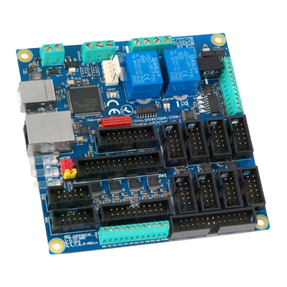
Page 9: Pokeys57Cnc Controller
PoPower12-25 PoKeys57CNC requires external 6-26 V power supply to be connected to the board in order for the device to operate correctly (device may not operate according to the specifications if the external power supply is not present). For this purpose we can use PoPower12-25. -
Page 10: Let's Start Connecting
Connect DC outputs (+V, -V) from the PoPower24-100 or PoPower48-320 to PoStep power supply connector. DC outputs from the PoPower12-25 connect to PoKeys57CNC power supply connector. Use screwdriver to attach. Power supply selection jumper on PoKeys57CNC board should be set on “EXT” www.poscope.com... -
Page 11: Stepper Motors
PoKeys57CNC and Mach4 – step by step guide Stepper motors Connect the stepper motor wires to the PoStep60-256 or PoStep25-32 driver output pins A, A’ and B, B’; marked on PCB. Use a table below for 4 or 8-wire stepper motor. -
Page 12: Make Custom Flat Cables
If you are using PoStep drivers, use the provided cables to connect the PoStep motor driver to PoKeys57CNC controller. Insert one end of the cable into the 10-pin IDC connector on the PoStep driver and insert the other end to one of the PoKeys57CNC motor connectors (labeled as MOTOR1 …... - Page 13 If your stepper motor driver has differential inputs (noticeable by the +/- signal pairs), we suggest wiring the negative signals (usually named PUL-, DIR- and ENA-) to GND of the PoKeys57CNC motor output and positive signals (named PUL+, DIR+ and ENA+) to step, direction and enable outputs of the PoKeys57CNC motor output.
-
Page 14: Connect Limit And Home Switches
We will take a look on how to connect limit and home switches of your CNC machine to the PoKeys57CNC controller. The PoKeys57CNC controller has screw terminals (labeled AX+) for one switch per each axis. Additional switches can be connected to the Limit/Home connector next to the screw terminals - adapter board 20-20 (https://www.poscope.com/product/adapter-board-20-20/) - Page 15 NPN (open-collector) type output. These can directly be connected to PoKeys57CNC inputs, as shown on the illustration below. Connect the GND of the sensor to GND of the sensor’s power supply and PoKeys57CNC GND. Connect the sensor’s signal output to PoKeys57CNC input terminal. Connect sensor’s positive power input to positive terminal of the sensor’s power supply.
-
Page 16: Connect Probe
Connect E-stop switch PoKeys57CNC is designed to include an emergency switch on the pendant – hence the input for the emergency switch is wired to the Pendant connector on the PoKeys57CNC. E-stop switch can be connected either to dedicated E-stop connector (red 4-pin connector) or to pendant connector (a combination of both is also allowed since both are wired in series). -
Page 17: Connecting Other Signals With The Pokeys57Cnc Device
Optocoupler inputs - active low Compatible PoKeys signals: PoKeys pin marked as either of DO5, DO5_D, OCOC, OCSSR or REL type in PoKeys57CNC specifications - suggestion: use OCOC or REL Wiring for DO5, DO5_D: Connect PoKeys GND to common ground of the external device, connect PoKeys pin to external device input. - Page 18 PoKeys57CNC and Mach4 – step by step guide input, connect the appropriate power supply (do not use +5V from the PoKeys device or the power supply used for powering the PoKeys device to avoid ground loops). Wiring for OCSSR: Connect PoKeys GND to common ground of the external device, connect PoKeys SSR output pin to external device input.
-
Page 19: Connecting Spindle Controller
If your spindle controller only has an on/off control input and the spindle speed is either constant or manually adjusted, use the appropriate PoKeys pin to drive the spindle controller on/off control input (check chapter Connecting other signals with the PoKeys57CNC device on page 17 for more information). - Page 20 The 0-10V analog output signal of the PoKeys device is generated by low-pass filtering the PWM signal (on pin 17 in case of PoKeys57CNC). Therefore, the signal is configured in PoKeys plugin for Mach4 under the ‘Miscellaneous’ tab. Set the PWM frequency to 20000 Hz, enable PWM on pin 17, select Pin 17 as the ‘Spindle output’...
-
Page 21: Connecting Spindle Speed Sensor
PoKeys57CNC and Mach4 – step by step guide Connecting spindle speed sensor PoKeys57CNC expects that the spindle speed sensor outputs a digital signal with one (index) pulse per spindle rotation. Connect the spindle speed signal to PoKeys pin 13 (pin 7 of the Encoders connector) and the sensor ground to PoKeys ground. -
Page 22: Enabling Threading Support
PoKeys57CNC and Mach4 – step by step guide Enabling threading support PoKeys57CNC supports threading operation with either index-only or encoder+index signals. Select ‘Enable threading support’ in the ‘Spindle’ tab of the PoKeys plugin configuration. Note that only lathe signal types for the spindle speed sensor can be selected. -
Page 23: Connect Other Peripherals
PoKeys57CNC and Mach4 – step by step guide Connect other peripherals If you are going to use Pendant and/or Keyboard, connect it to appropriate connector on PoKeys57CNC board. Use PoExtBus/PoNET connector for PoNETkbd48CNC. Final check and power up After connecting all together, make some final check before plugging power supply cable into AC socket. -
Page 24: Mapping Pokeys Digital Io Signals To Mach4 Io
PoKeys57CNC and Mach4 – step by step guide Mapping PoKeys digital IO signals to Mach4 IO PoKeys pins can be mapped to Mach4 digital input and output signals via the Config > Mach4 > Input signals or Outputs signals menu/configuration dialog. -
Page 25: Basic Configuration Of The Pokeys57Cnc Device
Convenience: since most of computers have built-in USB ports, connecting the PoKeys57CNC to a PC via a USB cable is the most convenient solution. However, this requires that the computer is in close proximity to the machine. On the other hand,... -
Page 26: Using Usb Connection
Fast USB interface (go to Device > USB > Enable Fast USB interface). Step 5: Remove the USB cable from PoKeys57CNC device, turn off the power to the PoKeys57CNC device, then re-apply the power and insert the USB cable again. The computer will find a new device and search for drivers. -
Page 27: Using Ethernet Connection
– this has to be done manually (if using direct connection to a PC) or is done by a router with a DHCP server. PoKeys57CNC devices are designed to operate in /24 subnets (network mask of 255.255.255.0). Other network configurations can also be used, but the operation of the devices will not be optimal (reduced capabilities of automatic device discovery). - Page 28 IP address. In order to configure the PoKeys57CNC device network settings, click on ‘Configure’ button and the following dialog will appear, allowing you to change between automatic IP retrieval (using DHCP) or manual configuration.
- Page 29 PoKeys57CNC and Mach4 – step by step guide device so that the device can be detected by the PoKeys application and configuration updated. Such address is recognized by the last part of the IP address being equal to .250. This address must not be used during normal operation of the device.
-
Page 30: Mach4 Setup
Downloads). Copy both plugin files and place them inside “Plugins” folder which is found inside Mach4 installation folder. 3. Connect PoKeys57CNC using USB or Ethernet cable to computer and run Mach4 software. When Mach4 opens, a welcome screen from the PoKeys plugin should appear. Click on “Open Add new device wizard”... - Page 31 PoKeys57CNC and Mach4 – step by step guide 4. Select your Pokeys device and click Next 5. In select Motor driver you use and check Pulse engine options Peripheral options and/or PoPendant, if you use one. You can also rename your device if you want.
- Page 32 PoKeys57CNC and Mach4 – step by step guide 7. Please restart Mach4 software. When Mach4 starts, ‘E-Stop condition!’ or ‘E-stop due to limit switch!’ text may appear in status list in the lower left corner of Mach4 window. This can happen due to the following causes: o E-Stop switch is pressed: to enable Mach4, release the E-stop switch o Polarity of E-stop switch is not configured correctly –...
- Page 33 Configure > Mach4 menu and switch to ‘Axis mapping’ tab. Check that the PoKeys57CNC motor outputs (Motor0...Motor7 correspond to MOTOR1…MOTOR8 connectors on the PoKeys57CNC device) are correctly assigned to each axis. Next, switch to ‘Motors’ tab and select Motor0 in the list on the right. Enter the correct ‘Counts per unit’, maximum velocity and acceleration that suit your machine...
- Page 34 PoKeys57CNC and Mach4 – step by step guide Option 2: select tab, click on Load G Code button and select FileOps roadrunner.tap from folder and then press button. Mach4Hobby\GcodeFiles Cycle Start Open user manual “PoKeys plugin for Mach4” that is provided with the Mach4 plugin for description of other available settings for the PoKeys device in Mach4.
- Page 35 5. PoLabs devices may be used in equipment that does not impose a threat to human life in case of the malfunctioning, such as: computer interfaces, office equipment, communications equipment, test and measurement equipment, audio and visual equipment, home electronic appliances, machine tools, personal electronic equipment, and industrial robots.
Need help?
Do you have a question about the PoKeys57CNC and is the answer not in the manual?
Questions and answers