Advertisement
Available languages
Available languages
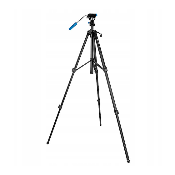
Tripod
Art.no 41-1225
Please read the entire instruction manual before using the product and
then save it for future reference. We reserve the right for any errors in
text or images and any necessary changes made to technical data. In
the event of technical problems or other queries, please contact our
Customer Services.
Product description
1. Handle
2. Legs
3. Leg locks
4. Feet
5. Height adjustment crank
6. Leg spreader lock knob
2
3
4
GREAT BRITAIN • CUSTOMER SERVICE tel. 020 8247 9300 e-mail customerservice@clasohlson.co.uk internet www.clasohlson.co.uk postal 10 – 13 Market Place, Kingston Upon Thames, Surrey, KT1 1JZ
7. Handle adjustment lock knob
8. Measuring instrument bubble vial
9. Graduated scale disc for tilt
10. Graduated scale disc for pan
11. Tripod bubble vial
12. Mounting plate
13. Mounting plate release catch
14. Pan lock knob
15. Tilt lock knob
16. Height adjustment lock knob
Assembly
5
1. Unpack the tripod and remove all packing materials.
2. Loosen the lock knob (6) and
1
spread the legs out (2) completely.
Tighten the lock knob.
6
3. Open the leg locks.
5. Slide the mounting plate release catch (13) to the side in order to
release the mounting plate (12).
a) Lift off the mounting plate and screw its fixing screw to your
instrument to fasten it.
b) Refit the mounting plate back into place and slide the release
catch back into its locked position, making sure that it is secure.
Operating instructions
12
7
13
1. Make sure that the tripod stands level by using the tripod's bubble
vial (11), the bubble should be centred within the target circle.
8
Correct any imbalances by adjusting the length of the feet (4).
14
2. Set the handle's (1) position by loosening the lock knob (7),
9
then position the handle into the desired position.
15
10
Tighten the lock knob.
3. Loosen the lock knob (16) for height adjustment and use
16
the crank (5), for precise adjustment, then tighten the lock knob.
4. Adjust the pan position by loosening the lock knob (14).
Use the handle to rotate the head into the desired pan
11
position and use the graduated scale on the panning disc (10)
for greater accuracy.
5. Set the tilt by loosening the lock knob (15) and tilt the handle to
the desired position. To help set the tilt level use the bubble vial (8)
and centre the bubble between the bubble lines. Use the graduated
scale on the tilting disc (9) for a more precise tilt angle.
Care and maintenance
Clean the product using a lightly moistened cloth. Use only mild
cleaning agents, never solvents or corrosive chemicals.
Responsible disposal
The product should be disposed of in accordance with local regulations.
If you are unsure how to proceed, contact your local council.
Specifications
Height
Weight
Material
4. Extend the legs to the desired
length and lock the leg locks.
68−175 cm
2.1 kg
Aluminium
Advertisement
Table of Contents

Summary of Contents for Cocraft 41-1225
- Page 1 7. Handle adjustment lock knob 8. Measuring instrument bubble vial 1. Make sure that the tripod stands level by using the tripod’s bubble Art.no 41-1225 vial (11), the bubble should be centred within the target circle. 9. Graduated scale disc for tilt Correct any imbalances by adjusting the length of the feet (4).
- Page 2 7. Låsvred för handtagsjustering 8. Libell för mätinstrument 1. Kontrollera att stativet står i våg med hjälp av libellen (11), bubblan Art.nr 41-1225 ska vara centrerad i cirkeln på fönstret. Korrigera genom att ändra 9. Vertikal gradskiva benens längd med de justerbara fötterna (4).
- Page 3 7. Låseratt for justering av håndtak 8. Libelle for måleinstrument 1. Kontroller at stativet står vannrett med hjelp av libellen (11). Art.nr. 41-1225 Boblen skal være sentrert i sirkelen på vinduet. Korrigere den 9. Vertikal gradeskive ved å endre lengden på beina på stativet.
- Page 4 Käyttö 7. Kahvan säädön lukitsin 8. Mittauslaitteen libelli 1. Varmista libellin (11) avulla, että jalusta on vaaterissa. Kuplan tulee Tuotenro 41-1225 olla ikkunassa näkyvän ympyrän keskellä. Korjaa muuttamalla 9. Pystytason astelevy jalkojen pituuksia säädettävillä jalkaosilla (4). Lue käyttöohje ennen tuotteen käyttöönottoa ja säilytä se tulevaa 10.
- Page 5 7. Drehriegel für die Griffeinstellung 8. Libelle für Messinstrument 1. Mithilfe der Libelle (11) sicherstellen, dass das Stativ im Gleichgewicht Art.Nr. 41-1225 ist. Hierfür muss sich die Blase in der Mitte des Kreises befinden. 9. Senkrechte Winkelskala Anpassungen können vorgenommen werden, indem die Länge Vor Inbetriebnahme die Bedienungsanleitung vollständig durchlesen...
Need help?
Do you have a question about the 41-1225 and is the answer not in the manual?
Questions and answers