Advertisement
Available languages
Available languages
Quick Links
.
Amp
DROP
Installation Instructions
Important Safety Instructions
Read these instructions. Keep these instructions. Heed all warnings. Do
not use this apparatus near water. Clean only with a dry cloth. Only use
attachments/accessories specified by the manufacturer. Unplug this
apparatus during lightning storms or when unused for long periods of
time. Refer all servicing to qualified service personnel. Servicing is
required when the apparatus has been damaged in any way, such as
power-supply cord or plug is damaged, liquid has been spilled or objects
have fallen into the apparatus, the apparatus has been exposed to rain or
moisture, does not operate normally, or has been dropped.
WARNING:
To reduce the risk of fire or electric shock, do not expose
this apparatus to rain or moisture.
The above instructions and warning apply only to the wall adapter.
Materials supplied
Electroline
Amp EDA-FT, EDA or ERA series
•
DROP
Wall adapter, 120 VAC, 15 VDC (or 120 VAC, 18 VDC for
•
two-way or return path models)
•
Electroline Power Inserter model EDA-IC-F (optional)
Installation
1. With two 1" #6 screws, mount the
brick or cement surface. Use nylon screw anchors on all mounting
surfaces other than wood.
2. To ground the
Amp, insert #6–#14 gauge grounding wire in the
DROP
hole at the top left edge of the
with a #2 Phillips head screwdriver.
3. Connect the CATV drop cable to the
4. Follow the Local Powering (A) or Remote Powering (B) instructions.
A.
For Local Powering
A1. Connect the subscriber's TV set(s) or cable converter(s) to the
output(s) on the
DROP
normally used to connect a cable modem or interactive set-top
box. Install 75-ohm terminators on any unused outputs.
A2. Use coaxial cable with a male F-type connector at each end to
connect the wall adapter to the
The wall adapter's F connector should be hand-tightened only.
The maximum recommended length for the cable is 100 feet
(30 meters), or 57 feet (17 meters) for the ERA 4100 model.
Figure A: Example of Local Powering
EDA and ERA Series
Hand-tighten
Insert ground wire
Mounting
hole
EDA-FT Series
Insert ground wire
Mounting
hole
Wall outlet power
adapter
*Unplug in order
to reset.
Hand-tighten
only
Troubleshooting:
If the
Amp is not working (power LED is off or dim, or output
DROP
signal is not amplified), check for a short circuit on the coaxial cable
between the
Amp and the wall adapter. Repair the short circuit,
DROP
and then reset the wall adapter as follows:
Unplug the wall adapter from the power source, and wait 20 seconds.
•
This resets the overload protection device (PTC), where applicable.
Plug the wall adapter back into the power source. The
•
green power LED should now be lit brightly. If the LED is dim,
repeat the reset procedure. If problems persist, contact
Electroline's technical support department.
305-0076 Ver.1 Copyright © 2001-2003 Electroline Equipment Inc., 8265 St-Michel Blvd., Montréal, Québec H1Z 3E4 Tel. 800-461-3344 or (514) 374-6335 Fax (514) 374-2257 info@electroline.com
TM
Amp on a wood, drywall,
DROP
Amp. Tighten the seizure screw
DROP
Amp's
connector.
DROP
RF IN
Amp. Note that the ERA 4100 is
Amp's
DROP
PWR
Wall outlet power
adapter
*Unplug in order
to reset.
CATV signal
only
input
Mounting
hole
EDA 2400
5 - 42 54 - 1000 MHz 6 kV
PWR
15 VDC 270 mA
OUT1+PWR
T M
OUT2
OUT3
OUT4
+7dB
+7dB
+7dB
+7dB
To TVs or cable
converters
Mounting
hole
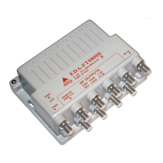
EDA-FT08000
PWR
5 - 4 2 5 4 -1000 MHz 6 kV
PWR 15 VDC
TM
LED
RF OUTPUTS
REMOTE
PWR
RF IN
PWR
(TOP)
FWD GAIN
3 dB
REV LOSS 10 dB
To TVs or cable
converters
CATV signal input
DROP
Materials not supplied
1" screws (#6) of an appropriate type for the mounting surface
•
nylon screw anchors (
•
•
coaxial cables with male F-type connectors
•
grounding wire (#6–#14 gauge)
B.
For Remote Powering
B1. With one 1" #6 screw, mount the Power Inserter on a wood,
drywall, brick or cement surface. Use a nylon screw anchor on
all mounting surfaces other than wood.
B2. Run a coaxial cable from the
Inserter to the subscriber's TV set or cable converter. Note that
the ERA 4100 model is normally connected to a cable modem or
interactive set-top box.
B3. Connect one end of the subscriber's additional TV sets or cable
converters to the remaining outputs on the
75-ohm terminators on any unused outputs. On all models, do not
connect anything to the
B4. Use coaxial cable with male F-type connectors at each end to
connect the Power Inserter's
Amp's remote power output (
DROP
B5. Use coaxial cable with male F-type connectors at each end to
connector.
connect the wall adapter to the Power Inserter's
connector. The wall adapter's F connector should be hand-
tightened only. The maximum recommended length for the
coaxial cables from the wall outlet to the
(30 meters), or 21 feet (6 meters) for the ERA 4100 model.
5. Plug the wall adapter into an indoor power outlet. If properly
connected, the
Figure B: Example of Remote Powering
EDA and ERA Series
Insert ground wire
Mounting
hole
EDA-FT Series
Hand-
tighten
Power Inserter
Amp's
For warranty, repair or return information, visit our Web site at
3
/
" x 1")
16
RF TV
port.
PWR
-
RF
PWR TO AMP
REMOTE PWR
Amp's green power LED will be lit.
DROP
CATV signal
input
DO NOT
CONNECT
Mounting
hole
EDA 2400
5 - 42
54 - 1000 MHz 6 kV
PWR
15 VDC 270 mA
T M
OUT1+PWR
OUT2
OUT3
OUT4
+7dB
+7dB
+7dB
+7dB
To TVs or cable converters
Wall outlet power
adapter
*Unplug in order
to reset.
Insert ground wire
Mounting
hole
only
To TV or cable
converter
EDA-FT08000
RF TV
5-1000
PWR
5 - 4 2 5 4 -1000 MHz 6 kV
MHz
PWR 15 VDC
TM
LED
RF OUTPUTS
REMOTE
RF-PWR
PWR
PWR
(TOP)
FWD GAIN
PWR
TO
REV LOSS 10 dB
IN
AMP
To TVs or cable
DO NOT
CONNECT
www.electroline.com
connector on the Power
Amp. Install
DROP
connector to the
or
).
OUT
1
PWR IN
Amp is 100 feet
DROP
Wall outlet
power adapter
*Unplug in order
to reset.
Hand-tighten only
To TV or cable
converter
Power Inserter
RF TV
5-1000
MHz
RF-PWR
PWR
TO
IN
AMP
Mounting
hole
RF IN
3 dB
converters
CATV signal input
Advertisement

Summary of Contents for Electroline DROPAmp EDA-FT Series
- Page 1 LED should now be lit brightly. If the LED is dim, repeat the reset procedure. If problems persist, contact www.electroline.com Electroline’s technical support department. 305-0076 Ver.1 Copyright © 2001-2003 Electroline Equipment Inc., 8265 St-Michel Blvd., Montréal, Québec H1Z 3E4 Tel. 800-461-3344 or (514) 374-6335 Fax (514) 374-2257 info@electroline.com...
- Page 2 Si les problèmes persistent, communiquer avec le service de soutien technique d’Electroline. 305-0076 Ver.1 Copyright © 2001-2003 Electroline Equipment Inc., 8265 St-Michel Blvd., Montréal, Québec H1Z 3E4 Tel. 800-461-3344 or (514) 374-6335 Fax (514) 374-2257 info@electroline.com...
Need help?
Do you have a question about the DROPAmp EDA-FT Series and is the answer not in the manual?
Questions and answers