Advertisement
K-Rain - Hydrotek Controllers Instructions
http://waterheatertimer.org/Woods-timers-and-manuals-old.html
HYDROTEK® 1000 / 2000 SINGLE STATION CONTROLLER INSTALLATION /
TROUBLESHOOTING
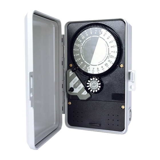
CONTROLLER FUNCTIONS
1. TIME DIAL - Rotates one clockwise revolution every 24 hours. Controller is
programmed for automatic (AUTO)operation with the insertion of timing pins in the
time dial holes. Once properly set, correct time of day is shown by the alignment of
the arrow labeled "TIME" with the time time shown on the time dial.
2. DAY WHEEL AND RETAINED PIN ASSEMBLY - Has 14 pin locations for a 2
week program. Controller will operate in AUTO only on the days programmed by the
depression of the day wheel pin. Once properly set, correct day is shown by the
alignment of the arrow labeled "DAY" with the day shown on the wheel.
3. AUTO-OFF-ON SWITCH KNOB - Indicates the function of the controller by
turning to ON, for manual operation, AUTO, for automatic operation and OFF,to stop
manual (ON) and automatic (AUTO) functions.
4. CHASSIS SCREWS - Secures controller chassis to enclosure.
5. ELECTRICAL CONNECTION STRIP (2000 SERIES) - Allows for input and
output electrical connection. Consult Electrical Circuit and Connection Diagrams
prior to wiring.
SETTING AND OPERATION INSTRUCTIONS
TO SET DAY OF WEEK AND TIME OF DAY:
Turn the Day Wheel until correct day is indicated by arrowed labeled "DAY" .
Turn the Time Dial CLOCKWISE until the correct time is indicated at the arrow
labeled "TIME".
CAUTION: Set Time Dial in CLOCKWISE direction only. DO NOT FORCE TIME
DIAL IN REVERSE DIRECTION.
Page 1 of 9
8/2/2005
Advertisement
Table of Contents

Summary of Contents for Hydrotek 1000
- Page 1 K-Rain - Hydrotek Controllers Instructions Page 1 of 9 http://waterheatertimer.org/Woods-timers-and-manuals-old.html HYDROTEK® 1000 / 2000 SINGLE STATION CONTROLLER INSTALLATION / TROUBLESHOOTING CONTROLLER FUNCTIONS 1. TIME DIAL - Rotates one clockwise revolution every 24 hours. Controller is programmed for automatic (AUTO)operation with the insertion of timing pins in the time dial holes.
-
Page 2: Electrical Connection Instructions
Auto. ELECTRICAL CONNECTION INSTRUCTIONS **PRIOR TO INSTALLATION OR SERVICE, DISCONNECT POWER TO CONTROLLER For 1000 Series Controllers: Remove controller face from enclosure by removing two chassis screws. Make wire connections as indicated by Electrical Circuit and Connection Diagram and secure connections with wire nuts provided. - Page 3 Properly ground controller. When reinstalling controller face or lower cover, do not trap wires between standoffs and screws. ELECTRICAL WIRING AND CIRCUIT DIAGRAMS 1000 Series 2000 Series SETTING AND CONNECTION INSTRUCTIONS Setting Instructions: To operate 2200 Series Controller every 10 minutes continuously, make sure that all 14 CYCLE WHEEL pins are pushed in.
-
Page 4: Wiring Diagram
Page 4 of 9 TIME DIAL in reverse direction. To operate Controller manually, turn AUTO-OFF-ON SWITCH to ON. When operation is no longer needed, turn back off. Electrical Connection Instructions CAUTIONS: **PRIOR TO INSTALLATION OR SERVICE, DISCONNECT POWER TO CONTROLLER** Ensure proper controller has been selected for the voltage application. -
Page 5: Parts List
1 hour black timing pin (6) 1009959 10 14 day retained pin set for day wheel 1000114 OTHER COMPONENTS Relay, 110 VAC, 60 Hz coil, double throw, single pole, 2 1000 1300110 Series 1320110 2000 Series Relay, 220 VAC, 60 Hz coil, double throw, single pole,... - Page 6 Page 6 of 9 2000 Series Transformer, 110 VAC input, 24 VAC, 30 VA output 1211027 Transformer, 220 VAC input, 24 VAC, 20 VA output 1222024 Key lock (2000 Series) 1009915 Pilot valve for model 2116 (w/o solenoid) 1003042 Solenoid with 110 VAC coil 6000813 TROUBLESHOOTING IMPORTANT...
-
Page 7: Installation Instructions
Page 7 of 9 SOLUTION: Turn Auto-Off-On switch to OFF. III. PROBLEM: Controller does not turn ON in manual mode. CAUSE: No power to controller. SOLUTION: Be sure that controller is properly wired as per Electrical Circuit and connection Diagram. SOLUTION: Check circuit breaker. - Page 8 Page 8 of 9 Rainswitch Control Switch (lower right) "ON" position - Allows Rainswitch to function and break water cycling if "WET". "OVERRIDE" position - Allows for manual operation of controller if Rainswitch is "WET". NOTE: If no Rainswitch is used, switch must be in position for controller to function. WIRE CONNECTION DIAGRAMS (Caution : always disconnect power at source prior to installing or servicing this unit)
- Page 9 Note: If no rainswitch is used, switch must be in "OVERRIDE" position for controller to function. Reinstall lower cover See 1000 / 2000 booklet for programming and operating instructions * May be used with Mini Clik II, Toro Rainswitch model 850-74, or other normally closed Rainswitch devices.
Need help?
Do you have a question about the 1000 and is the answer not in the manual?
Questions and answers
With a 4 zone system how do you turn off a particular zone with the 1114 unit
You cannot turn off a specific zone on the Hydrotek 1114 unit. The system operates purely sequentially using one valve and a cam mechanism that cycles through zones in a fixed order. Zones cannot be run or turned off individually.
This answer is automatically generated