Schaltbau CT1115/04 Series Manual
Single pole no power contactors for ac and dc
Hide thumbs
Also See for CT1115/04 Series:

Related Manuals for Schaltbau CT1115/04 Series

Summary of Contents for Schaltbau CT1115/04 Series
- Page 1 Contactors Contactors CT1115/04, CT1130/04 series Single Pole NO Power Contactors for AC and DC Manual C20/04-M.en...
- Page 2 Page 2/25 Rev.1.1 User Manual, Power contactors, series CT1115/04 and CT1130/04 Revision History: Rev.Level Date Page Description Name 26.10.2012 Part number of glue for ceramic protection insert Neuwieser changed from 13600310 to 13650290 24.10.2017 Functional decription, diagram of switching status, Kapfer page 10...
- Page 3 Furthermore, we refer to our “General Terms and Conditions of Sale (GCS) for Goods and Services”. Copyright notice Without prior written consent of Schaltbau GmbH, the operating instructions are not allowed to be electronically or mechanically reproduced – as a whole or in parts – be distributed, changed, transmitted, translated into another...
-
Page 4: Table Of Contents
Page 4/25 Rev.1.1 User Manual, Power contactors, series CT1115/04 and CT1130/04 Table of Contents Introduction ..............................5 Safety information ............................6 Electrical hazards ............................. 6 Safety notices ............................6 General application notes ......................... 6 Technical data ..............................7 Applied standards ............................7 Description .............................. -
Page 5: Introduction
Page 5/25 Rev.1.1 User Manual, Power contactors, series CT1115/04 and CT1130/04 CT1000 contactors are air switching components with arc breaking in ce- Introduction ramic. They use a highly sophisticated principle of arc control, combining the permanent-magnetic and electro-magnetic blow-out technique. This allows practically unrestricted operation for all AC and DC voltages and currents within the technical specification. -
Page 6: Safety Information
2 black protection caps is not permissible. All inspections and the replacement of components may only be performed by qualified personnel and must be done ac- cording to Schaltbau specification. All components which have to be replaced must be original components defined by Schaltbau. -
Page 7: Technical Data
Page 7/25 Rev.1.1 User Manual, Power contactors, series CT1115/04 and CT1130/04 Technical data Refer to catalogue C20, data sheets and measured drawings. Applied standards Refer to catalogue C20. EN60077-1: 2003-04 Railway applications - Electric equipment for rolling stock Part 1: General service conditions and general rules (IEC 60077-1:1999, modified) EN 60077-2: 2003-04... -
Page 8: Description
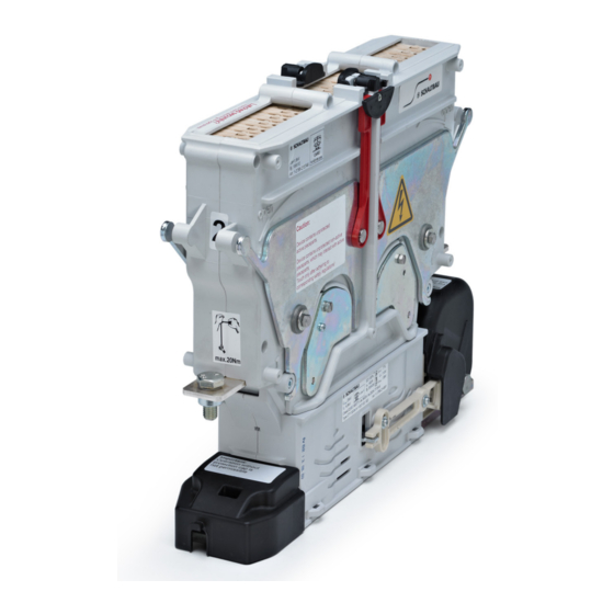
Page 8/25 Rev.1.1 User Manual, Power contactors, series CT1115/04 and CT1130/04 Description CT1000 contactors consist of two main modules: Lower Module: Magnetic drive (MD) with moving contact bridge (MC, not visible); base plate (BP); auxiliary contact group (AG); coil terminal group (TG);... -
Page 9: Upper Module
Page 9/25 Rev.1.1 User Manual, Power contactors, series CT1115/04 and CT1130/04 Auxiliary contact group (AG) Standard: - 1 contact to indicate the “well closed” position of the main con- tacts (EN60077: a1) - 1 contact to indicate the “well opened” position of the main con- tacts (EN60077: b0) - 2 NO/NC contacts Option:... -
Page 10: Functional Description
Page 10/25 Rev.1.1 User Manual, Power contactors, series CT1115/04 and CT1130/04 The diagram below shows the switching states of the CT1000 contactors. Functional description Typical values: Typical pull-in time: 120 ms Typical drop-off time: 60 ms Time constant of magnetic drive: app. -
Page 11: Order Code
Page 11/25 Rev.1.1 User Manual, Power contactors, series CT1115/04 and CT1130/04 Example: CT1130/04 V 110ET-00 001 Order code Number of poles 1-pole version Nominal voltage 1.5 kV 3 kV Conventional thermal current 400 A Mounting position Horizontal (yellow lock bars) Vertical (red lock bars Supply voltage 24 V... -
Page 12: Storage
Schaltbau recommends storing the contactors in the original packing box. Storage The contactors should be stored in a dry and suitable place. Schaltbau recommends using the original packing box for any return ship- Return shipments ments. If no original packing box is available care should be taken to pack the contactor in a way that prevents damage during the shipment. -
Page 13: Operating Position
The contactors (Lower Module) are fixed with 4 or more mounting screws, depending on the number of poles. The screws (and if applicable the nuts) must be steel grade 8.8. Schaltbau strongly recommends Schnorr-Washers (or similar) to secure the screws. The screws must be tightened with the rat- ed torque permissible for the screws and the nuts. -
Page 14: Electrical Requirements
Clean the surface of the mounting plate and the base-plate of the contactor Mechanical installation (Lower Module). Put the Lower Module on the mounting plate and secure with the appropri- ate screws using the correct tightening torque. Schaltbau strongly recom- mend Schnorr-Washers (or similar) to secure the screws. -
Page 15: Electrical Installation Of The Auxiliary Switches
Page 15/25 Rev.1.1 User Manual, Power contactors, series CT1115/04 and CT1130/04 Connect the wires for the auxiliary contacts. For the a1 and b0 contacts Electrical installation of (Switches S870) no polarity must be observed. For the general purpose the auxiliary switches contacts (Snap action switches S826) the polarity must be observed. -
Page 16: Mounting Of The Upper Module
The screws must be tightened with the rated torque (re- fer to label on the Upper Module). If you want to use current bars as recommended by Schaltbau, it is better to mount the bars below the main terminal. This way maintenance is much easier and the upper module can be removed without removing the current bars. -
Page 17: Electrical Installation Of The Earth Terminal
The use of press nuts in the current bars will simplify installa- tion and maintenance. Connect the earthing cable to the earth terminal with the appropriate screw. Electrical installation of Schaltbau strongly recommends a Schnorr-Washer (or similar) to secure the the earth terminal screw. Commissioning... -
Page 18: Maintenance
Page 18/25 Rev.1.1 User Manual, Power contactors, series CT1115/04 and CT1130/04 CT1000 contactors are maintenance-free within the rated mechanical Maintenance life time. The electrical life time depends on the number of switchings under heavy load conditions and may vary for different applications. In normal use, this corresponds to a decade-long operating period. -
Page 19: Spare Parts, Replacement Of Parts
However, in case of permanent heavy load switchings, of failures, of short- circuit switchings or in similar cases spare parts are offered by Schaltbau. Only original spare parts are to be used as a replacement MC CT1015/04... - Page 20 Page 20/25 Rev.1.1 User Manual, Power contactors, series CT1115/04 and CT1130/04 Remove and replace the fixed contacts (and ceramic protection insert) Put the Upper Module onto the table upside down on a smooth surface. The latching levers must be in the closed position to avoid damage Remove all four M5 screws with a number 8 socket wrench and put the screws and washers aside.
- Page 21 Page 21/25 Rev.1.1 User Manual, Power contactors, series CT1115/04 and CT1130/04 The following steps concerning the ceramic protection insert are for CT1030/04 only. The ceramic protection insert is fixed with glue. It Cut the glue carefully with a knife and pry it has to be replaced only in case of apparent wear open.
- Page 22 Page 22/25 Rev.1.1 User Manual, Power contactors, series CT1115/04 and CT1130/04 Reassembly of the fixed contacts Control the position of the nuts prior to assembly of the new fixed con- tacts. Replace the fixed contacts and push them into the locked position. Retighten the four M5 screws (Torque = 5 Nm).
- Page 23 Page 23/25 Rev.1.1 User Manual, Power contactors, series CT1115/04 and CT1130/04 Auxiliary contacts If the auxiliary switches have to be replaced all switches of one type (S826 or S870) should be replaced. Only original spare parts are to be used as a replacement CC CT1130/04 Protection cap, coil terminal CA CT1130/04...
- Page 24 Page 24/25 Rev.1.1 User Manual, Power contactors, series CT1115/04 and CT1130/04 Dismount and mount the switches or the S870 switch group one by one to avoid wrong mounting. If all switches are removed together and mounted again a readjustment of the frame is necessary. Changing the S870 assembly: Use a POZIDRIV ®...
- Page 25 High-voltage heaters ■ High-voltage roof equipment ■ Equipment for electric brakes ■ Design and engineering of train electrics to customer requirements We reserve the right to make technical alterations without prior notice. Printed in Germany For updated product information visit www.schaltbau-gmbh.com..
Need help?
Do you have a question about the CT1115/04 Series and is the answer not in the manual?
Questions and answers