
Summary of Contents for Ropox Smartbox II
- Page 1 Smartbox II, 30-69002 Brugermanual Montageanvisning Denne folder skal altid opbevares ved produktet! 6092 / Rev 001...
- Page 2 QR kode til montagefilm Scan koden med din smartphone Side 2 © ROPOX 2013...
-
Page 3: Table Of Contents
FUNKTIONSAFPRØVNING ..........................13 Funktionsafprøvning ..........................13 TILFØJELSE AF EKSTRA SMARTBOX/BOXE I ET EKSISTERENDE SYSTEM ........ 14 VEDLIGEHOLDELSE/ RENGØRING ......................14 Rengøring ..............................14 FEJLSØGNING SMARTBOXII ........................14 10.1 Beskrivelse af fejlmuligheder ........................14 REKLAMATION ..............................16 Side 3 © ROPOX 2013... -
Page 4: Anvendelse
Anvendelse Ønsker de at undgå unødvendig klemrisiko i forbindelse med installation og brug af Ropox højdeindstillelige køkken ramme systemer, kan De med fordel benytte vores Smartbox II. Det intelligente klemsikrings system anvendes i de situationer hvor der forekommer flere elektriske Ropox systemer, som er monteret op i umiddelbar forbindelse med hinanden. -
Page 5: Komponentliste
5. Forlængerledning 98002008: 1 stk. L=250 cm (sort) 6. Spiralledning 98002016: 1 stk. L =25-100 cm (sort) Montagedele: 96000155 Klæbesokkel 5 stk. 97702-460 Montagebeslag 1 stk. 95010610 M6x10 1 stk. 30-65500-008 Plademøtrik 1 stk. Kabelstrip 10 stk. Side 5 © ROPOX 2013... -
Page 6: Beskrivelse Af Smartbox-Systemet
Dvs. at sikkerhedsstoppene på alle Ropox produkterne kommunikere, hvormed farlige klemningszoner elimineres. Når man har monteret alle Ropox produkterne i køkkenet, så forbinder man alle Smartbox’ene via en kommunikationsledning. Herefter vil systemet register en hver aktivering af et sikkerhedsstop i netværket og stoppe alle op- og ned-kørsler indtil fastklemningen er fjernet. -
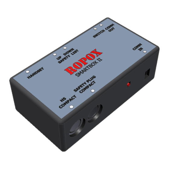
Page 7: Forklaring Til Smartbox
Tilslutning af sikkerhedskreds, der er monteret 2,2 kΩ modstand (gul) i den udgang der ikke bruges Håndbetjening Forbindes til indgangen for håndbetjeningen HS på Compact’en Forbindes til sikkerhedsindgangen på Compact’en LED lys (blink) ved aktivering af sikkerhedskreds Indgående kommunikation fra den forrige Smartbox Side 7 © ROPOX 2013... -
Page 8: Forbindelse Af Smartbox Til Compact
Forbindelse af Smartbox til Compact Ropox - håndbetjening Sikkerhedskreds Compact - kontrolboks Til Smartbox Kommunikations -kabel Fra Smartbox Sikkerheds-kabel Forbindelse mellem flere Smartbox’e ** Dette eksempel viser en opsætning med 3 Smartbox’e i systemet. ** På den første Smartbox i Kommunikationskablet fra På... -
Page 9: Sammenkobling Af Smartboxe
(se beskrivelsen på side 9) Der kan nu tilsluttes strøm til systemet. Smartboxe vil begynde at bippe Indstil skydekontakten på de 2 ende Smartboxe (se beskrivelsen på side 9), Smartboxene vil nu stoppe med at bippe Side 9 © ROPOX 2013... -
Page 10: Indstilling Af Smartbox
I dette tilfælde skal skydekontakten sættes til VENSTRE (væk fra center af boxen) 2. Smartboxen er placeret et sted midt i systemet. I dette tilfælde skal skydekontakten sættes til HØJRE (mod center af boxen) Side 10 © ROPOX 2013... -
Page 11: Montage Af Smartboxii
Montage af smartboxII Montage på aluminiumsbjælke: Montage på væg (Skruer er ikke inkluderet): Side 11 © ROPOX 2013... - Page 12 På Verti-InsideElectric placeres smartboxen på toppen af skabet som vist. På Diagonal placeres smartboxen på Skabspladen som vist Side 12 © ROPOX 2013...
-
Page 13: Funktionsafprøvning
Efter afsluttet installation og inden ibrugtagning skal der altid udføres en komplet afprøvning af alle funktioner på de installerede Ropox systemer. Efterfølgende skal der altid udføres funktionsafprøvning mindst én gang om året af kompetent personale: Se i øvrigt de tilhørende manualer. -
Page 14: Tilføjelse Af Ekstra Smartbox/Boxe I Et Eksisterende System
Kontroller at der ikke er nogle af Smartbox’ene som blinker. Hvis dette er tilfældet er sikkerhedsstoppet aktiveret på den aktuelle Smartbox. b. Strømmen til et eller flere af stellene er blevet afbrudt og dermed tillader sikkerhedsnetværket ikke at de øvrige kan køre. Side 14 © ROPOX 2013... -
Page 15: Reklamation
Reklamation Se general salgs & leverings betingelser på www.ropox.dk ROPOX A/S Ringstedgade 221 DK – 4700 Næstved Tel.: +45 55 75 05 00 Fax.: +45 55 75 05 50 E-mail: info@ropox.dk www.ropox.dk Side 15 © ROPOX 2013... - Page 16 Smartbox II, 30-69002 User Manual Mounting Instructions Keep this manual with the product at all times! 6092 / Rev 001...
- Page 17 QR code to mounting video Scan the code with your smartphone Page 17 © ROPOX 2013...
- Page 18 Performance test ............................28 ADDITION OF EXTRA SMARTBOXES TO AN EXISTING SYSTEM ............. 29 MAINTENANCE/CLEANING .......................... 29 Cleaning ..............................29 FAULT FINDING SMARTBOX ........................29 10.1 Description of possible errors ........................29 COMPLAINTS ..............................31 Page 18 © ROPOX 2013...
-
Page 19: Application
Application To avoid unnecessary jamming risk in connection with the installation and use of the Ropox height- adjustable kitchen frame systems the installation of our Smartbox II is the ideal solution. This intelligent safety system is used in situations when several electrically adjustable Ropox systems have been installed close to each other. -
Page 20: List Of Components
6. Spiral cord 98002016: 1 (one) L =25-100 cm (black) Mounting parts: 96000155 Adhesive mount 5 (five) 97702-460 mounting bracket 1 (one) 95010610 M6x10 1 (one) 30-65500-008 Plate nut 1 (one) Cable strip 10 (ten) Page 20 © ROPOX 2013... -
Page 21: Description Of The Smartbox System
This means that all safety stops of all Ropox products communicate, whereby dangerous jamming zones are eliminated. After installation of all the Ropox products in the kitchen, all Smartboxes must be connected via a communication cable. After that, the system will register any activation of a safety stop in the network and stop all upward and downward movements until the jamming situation has been eliminated. -
Page 22: Connection Of Smartbox
To be connected to the input port for the handset HS of the Compact To be connected to the safety input port of the Compact LED (flash) when safety circuit is activated Ingoing communication from preceding Smartbox Page 22 © ROPOX 2013... -
Page 23: Connection Of Smartbox To Compact
Connection of Smartbox to Compact Ropox – hand control Safety circuit Compact – control unit To Smartbox Communication cable From Smartbox Safety cable Connection between several Smartboxes ** This example shows an installation with 3 Smartboxes in the system. **... -
Page 24: Coupling Of 6 Smartboxes
Before connecting mains voltage to the system, ensure that all contacts have been set to centre (see description page 9) Now connect mains voltage. The Smartboxes will start beeping Set the two End-Smartboxes (see description page 9). The Smartboxes will stop beeping Page 24 © ROPOX 2013... -
Page 25: Setting Of Smartbox
THE LEFT (away from the centre of the box) 4. The Smartbox is located somewhere in the middle of the system. In that case, the slide contact must be set to THE RIGHT (towards the centre of the box) Page 25 © ROPOX 2013... -
Page 26: Mounting Of Smartbox
Mounting of Smartbox Mounting on aluminium beam Mounting on wall (screws are not included) When mounting the smartbox on verti-Inside Electric, place it on top of the cabinet as shown Page 26 © ROPOX 2013... - Page 27 When mounting the smartbox on verti-Inside Electric, place it on top of the cabinet as shown When mounting the smartbox on diagonal, place it on the front plate as shown Page 27 © ROPOX 2013...
-
Page 28: Performance Test
Performance test Performance test After correct installation and before use, all functions of the Ropox systems must be tested. After that, a performance test must be carried out at least once a year by competent personnel. Please also see corresponding manuals. -
Page 29: Addition Of Extra Smartboxes To An Existing System
Check that no Smartbox is flashing. In case of flashing, the safety stop of the specific Smartbox has been activated. b. The voltage to one or more frames has been disconnected, and the safety network does not allow the other frames to move. Page 29 © ROPOX 2013... -
Page 30: Complaints
Complaints See General Terms of Sale and Delivery on www.ropox.dk ROPOX A/S Ringstedgade 221 DK – 4700 Næstved Tel.: +45 55 75 05 00 Fax.: +45 55 75 05 50 E-mail: info@ropox.dk www.ropox.dk Page 30 © ROPOX 2013... - Page 31 Smartbox II, 30-69002 Benutzerhandbuch Montageanleitung Verbleibt beim Produkt! 6092 / 10.10.2014...
- Page 32 QR-Code für Montage-Video Scannen Sie den Code mit dem Smartphone Seite 32...
- Page 33 Inhaltsverzeichnis: ANWENDUNG ..............................34 KOMPONENTENLISTE ........................... 35 BESCHREIBUNG DES SMARTBOX-SYSTEMS ..................36 ANSCHLUSS DER SMARTBOX ........................37 Erläuterung zur Smartbox .......................... 37 Verbindung der Smartbox mit Compact ..................... 38 Zusammenschaltung mehrerer Smartboxen....................38 Zusammenschaltung von 6 Smartboxen ....................... 39 EINSTELLUNG DER SMARTBOX ......................... 40 Einstellung der Smartboxen im System.
-
Page 34: Anwendung
In solchen Fällen wird das System die Gefahr einer Einklemmung zwischen den einzelnen Einheiten reduzieren, als eine Ergänzung der üblichen Klemmleisten und Sicherheitsstopplatten. Die Smartbox darf nur in Zusammenhang mit Ropox Produkten wie FlexiElectric, VertiElectric oder 4SingleElectric verwendet werden, und nur dann wenn die Montage und der Gebrauch gemäß den Anweisungen dieses Handbuches und der übrigen Ropox Handbücher für die oben angeführten... -
Page 35: Komponentenliste
Komponentenliste Smartbox 30-69002: Die Smartbox umfasst: 1. Smartbox 98002102: 1 Stück 2. Verlängerungsschnur 96000597: 1 Stück 3. Kommunikationskabel 98002105: 1 Stück L=250 cm Stecker/Stecker 4. Kommunikationskabel 98002107: 1 Stück L=50 cm DIN 7-poliger Stecker 5. Verlängerungsschnur 98002008: 1 Stück L=250 cm (schwarz) 6. -
Page 36: Beschreibung Des Smartbox-Systems
Das bedeutet Kommunikation zwischen den Sicherheitsstops aller Ropox Produkte, wodurch gefährliche Einklemmungszonen vermieden werden. Nach Montage aller Ropox Produkte in der Küche sind die Smartboxen durch eine Kommunikationsleitung zu verbinden. Danach wird das System jede Aktivierung eines Sicherheitsstops im Netzwerk erfassen und alle Auf- und Abwärtsbewegungen stoppen, bis die Einklemmung eliminiert worden ist. -
Page 37: Anschluss Der Smartbox
Anschluss der Smartbox Erläuterung zur Smartbox Ausgehende Kommunikation zur nachgeschalteten Smartbox Kontakt zur Festlegung der ”ersten” und ”letzten” Smartbox des Systems LED (Blink) bei Aktivierung des Sicherheitskreises Anschluss des Sicherheitskreises. Ein 2,2 kΩ Widerstand (gelb) ist im nicht benutzten Ausgang montiert Handset An Eingang von Handset HS am Compact zu verbinden... -
Page 38: Verbindung Der Smartbox Mit Compact
Verbindung der Smartbox mit Compact Ropox- Handbedieneinheit Sicherheitskreis Compact-Steuereinheit Smartbox Kommunikations -kabel Von Smartbox Sicherheitskabel Zusammenschaltung mehrerer Smartboxen ** Dieses Beispiel zeigt eine Aufstellung mit 3 Smartboxen im System ** An der ersten Smartbox Kommunikations-kabel An der letzten Smartbox des Systems wird die... -
Page 39: Zusammenschaltung Von 6 Smartboxen
Zusammenschaltung von 6 Smartboxen End-Smartbox End-Smartbox Die obenstehende Abbildung zeigt ein Beispiel für eine Aufstellung mit 3 Tischplatten und 3 Schränken. Nach korrekter Montage aller Produkte sind alle Smartboxen des Systems mit einer Kommunikationslinie zu verbinden. Das ist die rote Linie der Abbildung. Beachten, dass die Smartboxen SERIENVERBUNDEN werden müssen, d.h. -
Page 40: Einstellung Der Smartbox
Einstellung der Smartbox Einstellung der Smartboxen im System. Zur Erreichung der korrekten Funktion des Smartbox-Netzwerkes, muss jede Smartbox je von ihrem Platz im System abhängig eingestellt werden. Das ist notwendig, da das System den Anfang und das Ende des Netzwerkes kennen muss. Das Beispiel auf Seite 8 zeigt die Einstellung des Schiebekontakts für jede Smartbox. -
Page 41: Montage Der Smartbox
Montage der Smartbox Montage am Aluminiumbalken Montage an der Wand (Schrauben werden nicht mitgeliefert) Seite 41... - Page 42 Die Smartbox, wie im Bild gezeigt, oben auf dem Schrank der Verti-InsideElectric plazieren Platzierung der Smartbox auf der Diagonal Seite 42...
-
Page 43: Funktionsprüfung
Funktionsprüfung Funktionsprüfung Nach beendigter Montage und vor Ingebrauchnahme muss eine komplette Überprüfung aller Funktionen der eingebauten Ropox Systeme durchgeführt werden. Eine Funktionsprüfung ist danach mindestens einmal pro Jahr von kompetentem Personal durchzuführen. Siehe entsprechende Benutzerhandbücher. Prüfung vor Einschaltung der Netzspannung: 27. -
Page 44: Ergänzung Eines Bestehenden Systems Durch Zusätzliche Smartboxen
Ergänzung eines bestehenden Systems durch zusätzliche Smartboxen 7. Die Netzspannung für alle Steuereinheiten und Smartboxen ausschalten 8. Die Kontakte aller Smartboxen für Mitte einstellen (siehe Beschreibung Seite 9) 9. Jetzt gemäß Punkt 4.3 auf Seite 7 und Punkt 4.4 auf Seite 8 vorgehen Wartung/Reinigung Reinigung WARNUNG... -
Page 45: Reklamation
Reklamation Siehe Allgemeine Verkaufs- und Lieferungsbedingungen auf www.ropox.dk ROPOX A/S Ringstedgade 221 DK – 4700 Næstved Tel.: +45 55 75 05 00 Fax.: +45 55 75 05 50 E-mail: info@ropox.dk www.ropox.dk Seite 45...
Need help?
Do you have a question about the Smartbox II and is the answer not in the manual?
Questions and answers