
Related Manuals for Realtek Ameba RTL8195AM

Summary of Contents for Realtek Ameba RTL8195AM
- Page 1 Realtek Ameba1 DEV01 User Manual This document define pin out of Ameba DEV. Version 1.5...
-
Page 2: Table Of Contents
Document Number: UM0058 _______________________________________________________________ Table of Contents Hardware block diagram ......................3 System requirements ......................4 Pin out reference ........................4 Pin out table ........................4 Pin out reference ......................5 Pin connection table ...................... 6 Antenna hardware setup ......................7 Peripherals support ......................... -
Page 3: Hardware Block Diagram
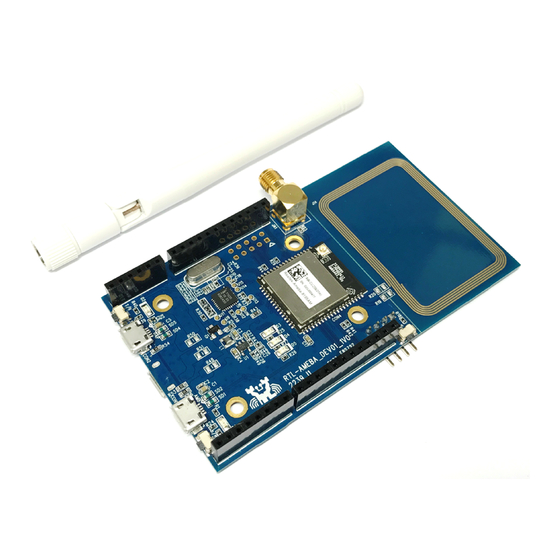
Document Number: UM0058 _______________________________________________________________ 1 Hardware block diagram IC: RTL8195AM DEV HDK version: RTL-AMEBA_DEV01_1v1 NFC Antenna Wi-Fi external Wi-Fi PCB ANT connector Antenna Ameba reset button J-TAG UART RTL8711AF DAP+DC Host +serial port DAP update DAP reset Mode button button March 8, 2016... -
Page 4: System Requirements
Document Number: UM0058 _______________________________________________________________ 2 System requirements Windows PC (XP, Vista, 7) USB type A to Micro-B USB cable x 1 RS-232 to UART board(debug) x 1, JTAG cable x1 (option) 3 Pin out reference 3.1 Pin out table Con DEV name Pin Net name Con DEV name... -
Page 5: Pin Out Reference
Document Number: UM0058 _______________________________________________________________ 3.2 Pin out reference GPIOA_6 GPIOD_6 GPIOA_7 GPIOD_7 GPIOA_5 DAC_CH0 GPIOD_4 ADC_CH2 GPIOD_5 ADC_CH1 GPIOA_4 ADC_CH1 GPIOA_3 GPIOA_2 GPIOB_4 GPIOB_5 5VDD GPIOC_0 VDD33 GPIOC_2 GPIOC_3 VDD33 GPIOC_1 GPIOA_1 VDD33 GPIOA_0 GPIOC_4 GPIOE_5 GPIOC_5 GPIOB_3 GPIOB_2 March 8, 2016... -
Page 6: Pin Connection Table
Document Number: UM0058 _______________________________________________________________ 3.3 Pin connection table GPIOB_2 GPIOB_3 GPIOC_5 I2C_SCL GPIOC_4 I2C_SDA VDD33 AREF GROUND GPIOC_1 D13/SCK/PWM1 GPIOC_3 D12/MISO/PWM3 GPIOC_2 D11/MOSI/PWM2 GPIOC_0 D10/CS/PWM0 GPIOB_5 D9/PWM1* GPIOB_4 D8/PWM0* GPIOA_2 GPIOA_3 GPIOA_4 GPIOD_5 D4/PWM1* GPIOD_4 D3/PWM2* GPIOA_5 GPIOA_7 TX/D1 GPIOA_6 RX/D0 March 8, 2016... -
Page 7: Antenna Hardware Setup
Document Number: UM0058 _______________________________________________________________ 4 Antenna hardware setup I-PEX/U.FL connector: R206 External antenna: R207 PCB antenna: R208 R207 R208 5 Peripherals support Debug UART: GPIOB_[0..1] March 8, 2016... -
Page 8: Pin Function Table Setup
Document Number: UM0058 _______________________________________________________________ JTAG: GPIOE_[0..4] 5.1 Pin function table setup Multiple functions are supported by group setup. For example: GPIOA_6(Rx), GPIOA_7(Tx), GPIOA_3(RTS) and GPIOA_5(CTS) are used if UART0 function. GPIOA_3(RTS) and GPIOA_5(CTS) can not be used as other functions. ... -
Page 9: J-Link/Jtag
Document Number: UM0058 _______________________________________________________________ 6.2 J-Link/JTAG Weld JTAG and log UART connectors to HDK board and connect with pitch 2.54mm 2x5pins connector. It is recommended to weld the connector on the bottom side. Users can connect extension boards from top side. March 8, 2016... - Page 10 Document Number: UM0058 _______________________________________________________________ JTAG 5V DC UART Dupont Line or 2.54mm 2x5 pins connector. Power On(Disable DAP mode) Holding TGT_NRESET button (J24, red-circled) then press Pdn button (J13, blur- circled). Release the button after power on. March 8, 2016...
-
Page 11: Dap Mode
Document Number: UM0058 _______________________________________________________________ 6.3 DAP mode In DAP mode, the DAP firmware can be updated. Holding TGT_NRESET button (J24, red-circled) then press nRESET button (J17, blur-circled). Then the DAP mode window will show up. March 8, 2016... - Page 12 Document Number: UM0058 _______________________________________________________________ DAP window will show up when entering DAP mode. March 8, 2016...
-
Page 13: Ameba1 Dev01 Pin Out
Document Number: UM0058 _______________________________________________________________ 7 Ameba1 DEV01 pin out March 8, 2016... -
Page 14: Sensor Board
Document Number: UM0058 _______________________________________________________________ 8 Sensor board Extension board: RTL-AMEBA_EXT B2_2V0 March 8, 2016... -
Page 15: Warning
Document Number: UM0058 _______________________________________________________________ 9 Warning 10.1 Federal Communication Commission Interference Statement This equipment has been tested and found to comply with the limits for a Class B digital device, pursuant to Part 15 of the FCC Rules. These limits are designed to provide reasonable protection against harmful interference in a residential installation. - Page 16 Document Number: UM0058 _______________________________________________________________ IMPORTANT NOTE: FCC Radiation Exposure Statement: This equipment complies with FCC radiation exposure limits set forth for an uncontrolled environment. This equipment should be installed and operated with minimum distance 20cm between the radiator & your body. IEEE 802.11b or 802.11g operation of this product in the U.S.A.
-
Page 17: Industry Canada Statement
Document Number: UM0058 _______________________________________________________________ may not cause harmful interference and (2) this device must accept any interference received, including interference that may cause undesired operation. LABEL OF THE END PRODUCT: The final end product must be labeled in a visible area with the following " Contains TX FCC ID: TX2-RTL8195AM ". - Page 18 Document Number: UM0058 _______________________________________________________________ To reduce potential radio interference to other users, the antenna type and its gain should be so chosen that the EIRP is not more than required for successful communication. This module is intended for OEM integrator. The OEM integrator is responsible for the compliance to all the rules that apply to the product into which this certified RF module is integrated.
- Page 19 Document Number: UM0058 _______________________________________________________________ French translation: Pour les produits disponibles aux Canada du marché, seul le canal 1 à 11 peuvent être exploités. Sélection d'autres canaux n'est pas possible. This device and its antenna(s) must not be co-located with any other transmitters except in accordance with IC multi-transmitter product procedures.
-
Page 20: Ncc 警語
Document Number: UM0058 _______________________________________________________________ d'antenne non inclus dans cette liste, ou dont le gain est supérieur au gain maximal indiqué, sont strictement interdits pour l'exploitation de l'émetteur. The following antenna type and max. gain be used and approved for the module: 1) Dipole antenna, max.
Need help?
Do you have a question about the Ameba RTL8195AM and is the answer not in the manual?
Questions and answers