Canon PowerShot G1 Service Manual
Hide thumbs
Also See for PowerShot G1:
- Software starter manual (114 pages) ,
- Firmware update installation instructions (7 pages) ,
- User manual (144 pages)
Table of Contents
Advertisement
Advertisement
Chapters
Table of Contents

Related Manuals for Canon PowerShot G1


Summary of Contents for Canon PowerShot G1
- Page 1 ENGLISH EDITION ENGLISH EDITION SERVICE MANUAL SERVICE MANUAL CANON DIGITAL CAMERA CANON DIGITAL CAMERA MENU MENU GENERAL INFORMATION REPAIR INFORMATION PARTS CATALOG ELECTRIC DIAGRAMS Digital Imaging Products Service Dept. Digital Imaging Products Service Dept.
- Page 3 PowerShot G1 C83-1004 SERVICE MANUAL...
- Page 4 Canon will release service manual reports as the need arises. In the event of major changes in the contents of this manual over a long or short period, Canon may issue new editions of this manual.
-
Page 5: Table Of Contents
GENERAL INFORMATION Product Strategy ........G1 1-1 Background to commerciarize ..G1 1-2 Product Objectives ......G1 1-3 Product Concept ......G2 Overview ..........G4 2-1 Features .......... G4 2-2 Design Concept ......G15 Exterior ..........G16 3-1 External Photos ......G16 3-2 6-dimensional Views ...... -
Page 7: Product Strategy
Their blanket strategy hinders Canon from catching up. In order for Canon to join the top tier (in terms of market share) from the year 2000, it is essential for us to expand our product line-up in the two directions described above to compete head-to-head with the other makers. -
Page 8: Product Concept
1-3 Product Concept The PowerShot G1 is the top-of-the-line PowerShot camera standing on the five pillars of full features, high image quality, operation ease, system accessories and application software. It is a high-end, compact digital camera targeting advanced amateurs and semi-professionals. (The reference pages are in brackets.) - Page 9 Operation Ease -Vari-angle LCD monitor [p.G10] -New UI for easy-to-read controls (Omni selector, stacked two mode dials, large display panel) [New! p.G10] -Switching between picture-taking and playback [New! p.G10] -Switchable AF mode (Continuous/Single) [New! p.G10] -Switchable video output format (NTSC/PAL) [New! p.G10] - Optical viewfinder with dioptric correction [p.G11] -Shutter-release sound like a film-based camera [New! p.G11] -Digital signal-processing IC + Buffer memory for stress-free operation [p.G11]...
-
Page 10: Overview
<Manual focus> Manual focusing is possible with the PowerShot G1. In sports or wildlife photography, you can set a specific focusing distance previously and take the shot when the subject comes into focus. - Page 11 <Manual exposure> The PowerShot G1 provides manual exposure as one of the exposure control modes. Manual exposure enables the user to set the aperture manually. The user can take pictures as he or she desires, with no automatic exposure adjustments from the camera.
- Page 12 -Movie recording and playback The PowerShot G1 can record a QVGA (320 X 240 pixels) video clip (with audio) at 15 frames per second up to approxi- mately 30 sec. The movie can be played back on the built-in LCD monitor or on a TV monitor. The movie is ideal for studying the subject’s movement or to record a sequence.
- Page 13 - Wireless controller The dedicated wireless controller can be used to operate the PowerShot G1. Press the DRIVE button to set the camera to the Self-timer mode. Then you can use the wireless controller to take still pictures, zoom the lens to the wide or telephoto end (Movie is shooting operation only) and display button, operate the Omni Selector (image forward and scroll), movie playback, display button, switch between single and multiple image playback and enlarge the image during playback.
- Page 14 -High-resolution zoom lens with advanced optical technologies The PowerShot G1 is equipped with a 7 - 21mm 3X zoom lens (equivalent to 34 - 102mm in 35mm format) that is suited for a wide range of picture-taking, from landscapes to snapshots. Also, the maximum aperture is f/2.0-2.5 which is the largest for a digital still camera.
- Page 15 PowerShot G1, so now RAW images require only approximately 60% the amount of memory necessary for the PowerShot A Series. The PowerShot G1 also enables playback of images on the LCD monitor or an external monitor. (Currently, the only digital cameras capable of this are the EOS D30, PowerShot G1 and the PowerShot Pro90.)
- Page 16 Note : AF mode is fixed to Single AF when LCD viewfinder is OFF. - Switchable video output format (NTSC/PAL) The PowerShot G1 provides the setting menu to set the video output format to either NTSC or PAL. This enables you to playback the images on a TV monitor in various countries.
- Page 17 The PowerShot G1 uses a Canon-developed digital signal processing IC. Despite the camera's high pixel count, the digital signal processing is quick response due to this IC. The PowerShot G1 also has a buffer memory where the captured image is temporarily stored. As the digital signal processing IC and buffer memory work in tandem, a short shooting interval of approx.
- Page 18 -Compatible with EX-series Speedlites mode for EOS cameras With its high pixel count and many features, the PowerShot G1 will likely to be used by advanced amateurs and pro users for creative shooting. Although it has a built-in flash, its maximum range is only 3.6 meters (ISO 100 equivalent) for telephoto shooting.
- Page 19 The ZoomBrowser EX (Windows)/ImageBrowser (Mac) programs were well received with the PowerShot S-series and improved with the IXY DIGITAL. The programs are now bundled with the PK500 and PowerShot G1. ZoomBrowser EX 2.4 is for simple retouching such as color and brightness adjustments and cropping. It also enables slide show playback on a PC, supports e-mail and DPOF editing.
- Page 20 -RemoteCapture 1.1 for remote picture-taking with a PC. The PowerShot G1 is bundled with the newly developed “RemoteCapture (USB only)” software. This software enables the camera to be remote controlled by a PC. The following remote control operations are possible with a PC:...
-
Page 21: Design Concept
-RS-232C TWAIN Driver 3.4/USB TWAIN Driver 3.4/Plug-in Module 3.4/ZoomBrowser EX 2.4/ImageBrowser 1.4 for adjusting image quality parameters. The PowerShot G1 provides the RAW mode to enable white balance, contrast, sharpness, and color saturation adjustments with the RS-232C TWAIN Driver 3.4/USB TWAIN Driver 3.4/Plug-in Module 3.4/ZoomBrowser EX 2.4/ImageBrowser 1.4. -
Page 22: Exterior
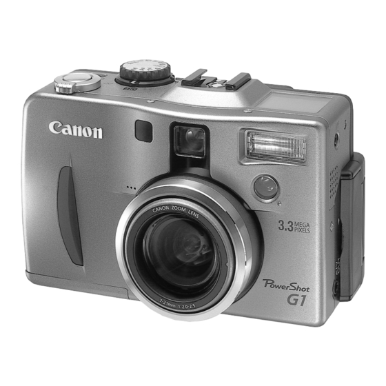
3. Exterior 3-1 External Photos... -
Page 23: 6-Dimensional Views
3-2 6-dimensional Views 119.3 (4.7) 63.8 (2.5) 115.9 (4.6) 52.7 (2.1) 78.9 76.8 (3.1) (3.0) 72.8 (2.9) 119.7 (4.7) 123.1 (4.8) Wide side : 39.3 (1.5) Tele side : 39.53 (1.56) Middle : 34.7 (1.4) Unit : mm (in.) *This figure is prototype. -
Page 24: Nomenclature And Functions
3-3 Nomenclature and Functions Main Dial Hot shoe Display Panel Mode Dial Continuous/Self-timer/ Wireless Controller Button Shutter Button Ring Zoom Lever Viewfinder Spot Metering/Enlarge Button Indicators Macro/JUMP Button Diopter Adjustment Lever Flash/Multi Button Omni Selector MENU Button SET Button AE Lock/FE Lock Button LCD Monitor Exposure/White Balance/AEB/ Flash Exposure Compensation Button... - Page 25 Display Panel Red-eye Reduction icon Single shot/Continuous shot icon Flash ON/OFF icon Wireless Controller icon Spot Metering icon Aperture Setting display Shutter Speed/Movie Shooting time display Manual Focus icon AE lock/FE Lock icon Battery Charge State icon JPEG compression icon Self-timer icon Resolution icon Information display...
-
Page 26: System
Also used for Film camera group’s products G General purpose Name of software Windows Macintosh Canon Utilities ZoomBrowser EX 2.4 (PhotoRecord 1.2 Canon Utilities ImageBrowser 1.4 Canon Utilities PhotoStitch 3.1 Canon Utilities PhotoStitch 3.1 Canon Utilities RemoteCapture 1.1 Canon Utilities RemoteCapture 1.1 Canon Digital Camera RS-232C T WAIN Driver 3.4... -
Page 28: Specifications
5. Specifications 5-1 Specifications <CCD> -Reading format Interline -Chip size 8.10 (H) X 6.64 (V) mm (0.3 X 0.2 in.) equivalent to 1/1.8-inch -Total pixels Approx. 3.34 million (2,140 (H) X 1,560 (V)) -Effective pixels Approx. 3.24 million (2,088 (H) X 1,550 (V)) <Lens>... - Page 29 CompactFlash™ (CF) card (Type I or Type II) -Storage capacity Above-written figures are measured under Canon’s standard conditions and may vary depending on the scene, subjects or camera settings. Small/N Small/F Small/SF M iddle/N M iddle/F M iddle/SF Large/N Large/F Large/SF...
- Page 30 Single image, all images (When "All images" is set, any images in the CF card captured with another camera or peripheral device (DCF format) are erased. Regarding Canon digital cameras, images taken by the PowerShot 600/600N, the PowerShot 350, Power...
- Page 31 LCD ON BP-511 : Approx. 260 images LCD OFF BP-511 : Approx. 800 images Canon’s standard conditions of measuring shooting capacity are as follows: Normal temperature (23 Celsius degrees). LCD viewfinder is ON. Shoot images at wide angle end and at telephoto end alternately with 20 seconds intervals.
- Page 32 Since the PowerShot G1/Pro90 IS’s RAW has an internal JPEG file for playback, a full-screen image is displayed. However, if the RAW from the PowerShot A50 and older models is played back with the PowerShot G1/Pro90 IS, thumbnails will be displayed.
-
Page 33: System Requirements
5-2 System requirements (Canon Digital Camera Solution Disk 2.0 is required for installing software) [Microsoft Windows ® 95, Windows ® 98, WindowsNT ® 4.0 and Windows ® 2000] -Computer Model IBM PC/AT or compatible ® ® Microsoft Windows 95, Windows 98 (including Second Edition), ®... - Page 34 <Accessories’ Compatibility> PowerShot G1 PowerShot PRO90 IS Note <Battery> NB-6N for PS 600, 600N NB-5H for PS A, S series NB-4H for PS Pro70 NB-1L for IXY DIGITAL/DIGITAL IXUS/PS S100 DIGITAL ELPH BP-511 for Video Camera FV-2, FV-10 <Adapter/Charger> CB-15N...
- Page 35 PowerShot G1 PowerShot PRO90 IS Note <Cable etc.> VC-100 for PS A, S series VC-200 for IXY DIGITAL/DIGITAL IXUS/PS S100 DIGITAL ELPH AVC-DC100 for G1, PS PRO90 IS IFC98B/15 for PS600, 600N IFCDOS/V for PS600, 600N IFC-100PC for PS A series, PS Pro70...
-
Page 36: Main Accessory Specifications
*Even if the user is shooting in normal AF mode with the Close-up Lens attached, the camera will focus within a range of 200 - 250 mm (0.7 - 0.8 ft.). -Attaching to the camera : 58mm standard filter screw (The LA-DC58 is required to attach the 250D to PowerShot G1) -Weight : Approx. 80g (2.8 oz) <Conversion Lens Adapter LA-DC58>... - Page 37 <AV Cable AVC-DC100> 1500+/-100 (59.1+/- 4.0) - RCA pin plug-L plug 150+/-30 (6.0+/- 1.2) 60 (2.4) - See Fig. 5-4 for the dimensions. Yellow Black Fig. 5-4 AV Cable AVC-DC100 dimensions (mm (in.)) <Battery Pack BP-511> -Type : Lithium-ion secondary battery -Nominal voltage : DC 7.4 V -Nominal capacity...
- Page 38 <Charge Adapter/Car Battery Cable Kit CR-560> <Charge Adapter CG-560> -Input voltage : DC 9.5 V -Input current : DC 2.5A 2.7A (DC 9.5V, while charging the battery pack) -Nominal output : Battery terminals : DC 8.4V 1.6A (while charging the BP-511) DC OUT terminals : DC 8.4V 1.6A (with the adapter) -Charging detection : Voltage/current detection by a microprocessor 93 (3.7)
-
Page 39: Operation Procedures
6. Operation 6-1 Operating Procedures <Shooting Operation> <Basic picture-taking (Auto mode)> -Set the main dial to “Shooting mode” and set the mode dial to “Auto. ” -Frame the subject and press the shutter button. -Using the Optical Viewfinder- Look through the optical viewfinder, frame the subject, then press the shutter button halfway. The Indicator will light in green and the beep will sound twice. - Page 40 <Macro feature (Auto/Creative zone/Portrait/B&W/StitchAssist/Movie)> -Press the MACRO button and use the Optical viewfinder or LCD monitor to frame the subject, then press the shutter button halfway. The macro indicator lights yellow. -The camera operation when the shutter button is pressed halfway and completely is the same as with “Basic picture- taking.”...
- Page 41 <AE Lock/FE Lock (Enabled in all Creative Zone except for M, at EVF only.)> -Set the Mode Dial to a Creative Zone mode. -AE lock takes effect at SW1 or when the AE lock/FE Lock button is pressed while there is no other camera operation. FE is locked in Flash mode is set.
- Page 42 -Press the Omni Selector to select the desired item, then press the SET button. The following items can be set: -Single Erase -Erase all -Protect -Rotate (0 degree, 90 degrees, 270 degrees) -Slide Show -Print Order (Marks the images to be printed with Canon Digital Printer CD-300 and the printers compatible with DPOF)
- Page 43 <Erasing Images> -In the play mode, press the MENU button to display the Play Menu. -Select "Single Erase" or "Erase All", then press the SET button. -When Single Erase has been selected, the image displayed before the Play Menu appeared will be displayed. Press the Omni Selector to select the image to be erased.
- Page 45 REPAIR INFORMATION Troubleshooting ........R1 1-1 When an Error Code is Displayed ..R1 1-2 When a Problem Occurs ....R3 Disassembly and Assembly ....R5 2-1 Required Tools ........ R5 2-2 Procedure ........R5 2-3 Removal of Main Parts/Units .... R6 2-4 Disassembly of Main Units .....
-
Page 47: Troubleshooting
1 Troubleshooting 1-1 When an Error Code is Displayed [Remedy] • Check for any abnormalities in the mounting of probable faulty parts or connector connections referring to the table below. • Try replacing probable faulty parts referring to the table below. [NOTE] •... - Page 48 Error Cause and Probable Faulty Part Name Occurrence Conditions See Page * Numbers in parentheses ( ) are the symbols on the Code most probable circuit component. CF NO SPACE When the CF becomes full during R15,E1,E2 writing of photographed images to CF, writing is repeatedly performed with the JPEG compression ratio succes- sively increased to reduce the size of...
-
Page 49: When A Problem Occurs
1-2 When a Problem Occurs [Remedy] • Check for any abnormalities in the mounting of probable faulty parts or connector connections referring to the table below. • Try replacing probable faulty parts referring to the table below. [NOTE] • Adjustments must be performed after the part has been replaced. For details, see “3 Adjustments.” Problem Cause and Probable Faulty Part See Page... - Page 50 Cause and Probable Faulty Part Problem See Page * Numbers in parentheses ( ) are the symbols on the most probable circuit (when an error code is not displayed) component. The External Flash does not fire. TOP MODULE UNIT(IC1/CN1) R44,E5,E6 ACC.
-
Page 51: Disassembly And Assembly
Refer to R34, R52 (LUBE,LOGENEST RAMBDA A-74 ) 2-2 Procedure The following flowchart shows the procedure for disassembling the PowerShot G1. To assemble, follow the procedure in reverse. *( ) : denotes the page to be referenced. [Relations among Line-Connected Units] 1.To disassemble the lower unit, disassemble the upper unit. - Page 52 STEP1 Remove the screws. STEP2 Remove the screws. STEP3 Remove the FRONT COVER UNIT. STEP4 Bleed the capacitor. Warning-High Voltage! Do not touch the CAPACITOR terminal . Be sure to bleed the capacitor by the discharge resistor (approx. 1kΩ/5W). CAPACITOR terminal <Screw>...
- Page 53 STEP5 FRONT COVER UNIT Remove the FRONT RING. FRONT RING...
- Page 54 STEP1 Remove the screws. c x 2 STEP2 Remove the screws. STEP3 Remove the REAR COVER UNIT. STEP4 Remove the SELECTOR SPRING. <Screw> : CD1-3278-000 (M1.7mm, L3.0mm, Black) : CD1-3279-000 (M1.7mm, L4.0mm, Gray Metallic) : XA4-9170-409 (M1.7mm, L4.0mm, Self-Tap, Black)
- Page 55 STEP5 Remove the screws. h x 2 STEP6 Remove each of the parts. REAR COVER UNIT LCD LOCK STOPPER LCD LOCK SPRING LCD LOCK SLIDER <Screw> : XA4-9170-359 (M1.7mm, L3.5mm, Self-Tap, Black)
- Page 56 STEP1 Remove the JACK COVER. STEP2 Remove the screws. JACK COVER STEP3 Remove the SIDE COVER. SIDE COVER <Screw> : CD1-3278-000 (M1.7mm, L3.0mm, Black)
- Page 57 STEP1 Disconnect the flex. Warning ! g x 2 Disconnect the flex in the direction of the arrow. Otherwise, the connector may be damaged. STEP2 Remove the screws. STEP3 Disconnect the flex. STEP4 Remove the TOP UNIT. TOP UNIT <Screw> : CD1-3280-000 (M1.7mm, L3.5mm, Self-Tap, Gray Metallic) : XA1-7170-167 (M1.7mm, L1.6mm)
- Page 58 STEP1 Remove the screws. STEP2 Remove the CF CLICKING SPRING1 and CF CLICKING SPRING2. STEP3 Remove the CF COVER. CF COVER CF CLICKING SPRING2 CF CLICKING SPRING1 <Screw> : XA4-9170-359 (M1.7mm, L3.5mm, Self-Tap, Black)
- Page 59 STEP1 Disconnect the cables. STEP2 Remove the screw. STEP3 Disconnect the cable. STEP4 Remove the screw. STEP5 Remove the FLASH/SPEAKER UNIT. FLASH/SPEAKER UNIT <Screw> : XA1-7170-307 (M1.7mm, L3.0mm)
- Page 60 STEP1 Disconnect the flex. STEP2 Remove the screws. STEP3 Remove the JACK PCB ASS’Y. JACK PCB ASS’Y <Screw> : XA1-7170-307 (M1.7mm, L3.0mm)
- Page 61 STEP1 Remove the screw. STEP2 Remove the MAIN SHEET. MAIN SHEET STEP3 Disconnect the cables and the flex. STEP4 Remove the screw. MAIN PCB ASS’Y STEP5 Remove the MAIN PCB ASS’Y. STEP6 Remove the screw. MAIN SHEET STEP7 Remove the MAIN SHEET. <Screw>...
- Page 62 STEP1 Disconnect the cables. STEP2 Remove the screws. h x 3 STEP3 Remove the screws. STEP4 Disconnect the flex adhered by double-sided tape. At Assembly Affix double-sided tape to the rear side. A : 5mm x 5mm B : 2mm x 5mm <Screw>...
- Page 63 STEP5 Remove the REAR PLATE UNIT.
- Page 64 STEP1 j x 3 Remove the screws. STEP2 Remove the FINDER UNIT. FINDER UNIT At Assembly For details on how to assemble the FINDER UNIT and OPTICAL UNIT, see the following page. <Screw> : XA4-9170-407 (M1.7mm, L4.0mm, Self-Tap)
- Page 65 Assembling the FINDER UNIT and OPTICAL UNIT STEP1 OPTICAL UNIT Rotate the gear with your finger, and align line X on the lens barrel with line Y on the cam ring. Line Y Line X Line Y Line X STEP2 FINDER UNIT Rotate the gear with your finger in the direction of the arrow to the limit.
- Page 66 STEP3 Rotate the gear by about 7/8 of a turn from the state in STEP 2 to align holes A and B. Hole B Hole A STEP4 Pass the 1.2 mm dia. wire through holes A and B to lock the gear. * During this operation, look through the FINDER to make sure that the lens is at the WIDE end.
- Page 67 STEP1 Remove the screws. STEP2 Remove the screws. STEP3 Remove the OPTICAL UNIT. OPTICAL UNIT <Screw> : XA1-7170-407 (M1.7mm, L4.0mm)
- Page 68 STEP4 LENS PLATE Remove the LENS PLATE. (Adhesive) OPTICAL UNIT...
- Page 69 STEP1 Remove the screws. l x 2 g x 2 PUSH STEP2 Remove the CF UNIT. CF UNIT <Screw> : XA1-7170-167 (M1.7mm, L1.6mm) : XA4-9170-609 (M1.7mm, L6.0mm, Self-Tap, Black)
- Page 70 STEP1 Remove the CF PLATE. CF PLATE (Aadhesive) STEP2 Remove the screws. e x 2 STEP3 Remove the BATTERY BOX UNIT. <Screw> : XA4-9170-409 (M1.7mm, L4.0mm, Self-Tap, Black)
- Page 71 STEP1 Remove the screws. i x 2 STEP2 LCD/HINGE UNIT Remove the LCD/HINGE UNIT. <Screw> : XA1-7170-307 (M1.7mm, L3.0mm)
- Page 72 STEP1 Remove the screws. i x 3 STEP2 Remove the SUB FRAME. STEP3 Remove the screws. i x 2 SUB FRAME MINI FRAME* * The MINI FRAME is not included in the SUB FRAME (CD1-3253-000). <Screw> : XA1-7170-307 (M1.7mm, L3.0mm)
- Page 73 STEP1 Remove the screws. i x 3 STEP2 Remove the DC/DC CONVERTER PCB ASS’Y. STEP3 Remove the VID FPC. VID FPC* * The VID FPC is not included in the DC/DC CONVERTER PCB ASS’Y (CM1-1076-000). DC/DC CONVERTER PCB ASS’Y <Screw> : XA1-7170-307 (M1.7mm, L3.0mm)
- Page 74 STEP1 Remove the screws. i x 3 STEP2 Remove the TRIPOD BASE. MAIN FRAME TRIPOD BASE <Screw> : XA1-7170-307 (M1.7mm, L3.0mm)
- Page 75 STEP1 Remove the screws. g x 4 h x 2 STEP2 B/W LCD UNIT Disassemble the DIAL/COVER UNIT and B/W LCD UNIT. DIAL/COVER UNIT At Assembly The DIAL/COVER UNIT and B/W LCD UNIT must be assembled with the MAIN DIAL BRUSH, MODE DIAL BRUSH, MAIN DIAL and MODE DIAL rotated in the direction of the arrows to the limit.
- Page 76 1) ZOOM LEVER etc. STEP1 SELF TIMER BUTTON Remove the SELF TIMER BUTTON. STEP2 Remove the ZOOM BRUSH Claw ZOOM BRUSH STEP3 Remove the screws. g x 2 <Screw> : XA1-7170-167 (M1.7mm, L1.6mm)
- Page 77 STEP4 ZOOM SPRING Remove the ZOOM SPRING STEP5 Remove the E RING ZOOM LEVER E RING RELEASE SPRING...
- Page 78 RELEASE CAP At Assembly Glue with DIA BOND. RELEASE BUTTON 2) MODE DIAL etc. STEP1 Remove the screw. STEP2 Remove the MODE CONNECTIVE PLATE. At Assembly Set the MODE DIAL to “ M ” and attach the MODE CONNECTIVE PLATE at the position shown in the photograph on the left.
- Page 79 STEP3 Remove the MODE DIAL. MODE DIAL MODE DIAL PLATE MODE DIAL At Assembly Apply a coat of DIA BOND. STEP4 Remove the MODE CLICK SPRING. MODE CLICK SPRING...
- Page 80 STEP5 Remove the MAIN DIAL. MAIN DIAL STEP6 Remove the MODE CLICK SPRING. MODE CLICK SPRING At Assembly Apply a coat of LOGENEST LAMBDA A-74 to the sliding surfaces of the MODE DIAL and MAIN DIAL.
- Page 81 3) ACC. SHOE etc. STEP1 Remove the screw. STEP2 Remove the ACC. DETECT BASE2. ACC. DETECT BASE2 STEP3 Remove the ACC. DETECT PLATE. ACC. DETECT PLATE <Screw> : XA1-7170-307 (M1.7mm, L3.0mm)
- Page 82 STEP4 ACC. SHOE PIN Remove the ACC. SHOE PIN. STEP5 ACC. DETECT BASE1 Remove the ACC. DETECT BASE1. STEP6 Insert tweezers under the ACC. SHOE SPRING. Warning ! Take care not to scratch parts.
- Page 83 STEP7 Remove the ACC. SHOE SPRING. At Assembly Apply a coat of DIA BOND. ACC. SHOE SPRING STEP8 Remove the screws. m x 4 At Assembly After tightening the screws, apply a coat of THREE BOND 1401C to these screws. ACC.
- Page 84 4) ACC. SHOE FPC etc. STEP9 Remove the screw. STEP10 Remove the ACC. SHOE FRAME. STEP11 Remove the solder. ACC. SHOE FRAME STEP12 Remove the ACC. SHOE FPC. ACC. SHOE FPC <Screw> : XA4-9170-359 (M1.7mm, L3.5mm, Self-Tap, Black)
- Page 85 STEP13 ACC. CONTACT UNIT Remove the ACC. CONTACT UNIT. TOP COVER UNIT...
- Page 86 1) MAIN DIAL BRUSH etc. STEP1 Remove the E RING. E RING STEP2 MODE BASE PLATE Remove the MODE BASE PLATE.
- Page 87 STEP3 Remove the MAIN DIAL BRUSH and MODE DIAL BRUSH. MODE DIAL BRUSH MAIN DIAL BRUSH STEP4 MODE DIAL FRAME Remove the MODE DIAL FRAME.
- Page 88 2) B/W LCD PANEL etc. STEP1 Remove the two B/W LCD CLIPs. Claw Claw B/W LCD CLIP x 2 STEP2 Remove the B/W LCD PANEL. At Assembly Align the protruding section on the B/W LCD PANEL with the indent on the B/W LCD HOLDER.
- Page 89 STEP3 Remove the two CONTACT RUBBERs. At Assembly CONTACT RUBBER direction CONTACT RUBBER CONTACT RUBBER x 2 STEP4 Remove the B/W LCD HOLDER. B/W LCD HOLDER STEP5 Remove the sections adhered by double-sided tape. At Assembly Affix double-sided tape to the rear side.
- Page 90 STEP6 Remove the TOP MODULE UNIT. TOP MODULE UNIT B/W LCD FRAME...
- Page 91 1) SPEAKER UNIT etc. STEP1 SPEAKER BUSH Remove the SPEAKER BUSH. At Assembly Apply a coat of DIA BOND. STEP2 Remove the SPEAKER UNIT. SPEAKER UNIT At Assembly Cut the double-sided tape to the following dimension for use. 5mm x 5mm...
- Page 92 2) AF LED FPC etc. STEP1 Remove the screw. STEP2 FLASH UNIT STEP3 Disconnect the flex section. At Assembly Apply a coat of DIA BOND. <Screw> : XA4-9170-359 (M1.7mm, L3.5mm, Self-Tap, Black)
- Page 93 STEP4 AF LED LEAD Remove the solder from the cables. BLACK AF LED FPC AF LED LENS AF LED HOLDER At Assembly Apply a coat SEMEDYNE SUPER X to the part indicated [...
- Page 94 1 ) MIC .UNI T etc. STEP1 Remove the MIC. HOLDER. STEP2 Remove the FLASH IC HOLDER. At Assembly Cut the double-sided tape to MIC. HOLDER the following dimension for use. 5mm x 5mm FLASH IC HOLDER STEP3 Remove the solder from the cables. BLACK MIC.
- Page 95 2) BUTTON PCB ASS’Y STEP1 i x 2 Remove the screws. STEP2 Remove the SEL. BUTTON BASE. STEP3 Remove the sections adhered by double-sided tape. At Assembly Affix double-sided tape to the rear side. A : 5mm x 10mm B : 5mm x 10mm C : 5mm x 10mm BUTTON PCB ASS’Y REAR FRAME...
- Page 96 1) BATTERY COVER STEP1 Open the BATTERY COVER. STEP2 Rotate the BATTERY COVER to the side. STEP3 Remove the BATTERY COVER. BATTERY COVER DATE BATTERY HOLDER...
- Page 97 2) BATTERY LOCK SWITCH etc. STEP1 Remove the screw. STEP2 Remove the solder from the cables. BATTERY LOCK SWITCH BLACK SUB LEAD1 3) BATTERY LOCK OPENER etc. STEP1 Remove the screw. <Screw> : XA4-9170-359 (M1.7mm, L3.5mm, Self-Tap, Black) : XA4-9200-657 (M2.0mm, L6.5mm, Self-Tap)
- Page 98 STEP2 BATTERY COVER LOCK Remove each of the parts. BATTERY LOCK SPRING At Assembly BATTERY COVER OPENER Apply a coat of LOGENEST LAMBDA A-74 to the sliding surfaces. 4) BATTERY EJECT SPRING etc. STEP1 Remove the screws. Claw STEP2 l x 2 Remove the BATTERY BOX COVER.
- Page 99 STEP3 Remove the BATTERY EJECT SPRING. BATTERY EJECT SPRING 5) POWER LEAD etc. RED(POWER LEAD) BLACK(DATE LEAD) STEP1 Remove the solder from each of the cables. BLACK(POWER LEAD) RED(DATE LEAD) DATE LEAD* *DATE LEAD = SUB LEAD (CK2-1169-000) BATTERY BOX MAIN UNIT POWER LEAD...
- Page 100 STEP1 Remove the LCD PLATE. STEP2 LCD PLATE Remove the screws. (Adhesive) c x 2 STEP3 Remove the screws. c x 2 STEP4 Remove the LCD TOP COVER. <Screw> : CD1-3278-000 (M1.7mm, L3.0mm, Black)
- Page 101 STEP5 Remove the screw. STEP6 Disconnect the cables. STEP7 Remove the HINGE UNIT. <Screw> : XA1-7170-307 (M1.7mm, L3.0mm)
- Page 102 STEP8 Remove the screws. c x 2 STEP9 Remove the HINGE COVER. HINGE COVER HINGE UNIT STEP10 Remove the screw. <Screw> : CD1-3278-000 (M1.7mm, L3.0mm, Black) : XA1-7170-307 (M1.7mm, L3.0mm)
- Page 103 STEP11 Remove the NUT PLATE. NUT PLATE STEP12 Remove the LCD FRAME COVER. LCD FRAME COVER STEP13 Disconnect the flex.
- Page 104 STEP14 Remove the LCD PANEL. LCD PANEL At Assembly Be sure to remove the protective sheet attached to service parts. STEP15 Remove the solder. STEP16 Remove the LCD PCB ASS’Y.
- Page 105 LCD PCB ASS’Y LCD SHEET BACK LIGHT UNIT...
- Page 106 ↓ ↓ ↓...
-
Page 108: Before Starting Electrical Adjustment
(“Imaging Process Adjustment” is impossible when the RS-232C TW AIN driver is used.) 3-3-2 Installing the Adjustment Software Double click : \AdjustmentSoftware \ PowerShot G1 \ English* \ Setup.exe \ , in this CD-ROM. *When you perform the adjustment in the U.S.A., double click the Setup.exe in the “USA” folder. - Page 109 3-3-3 Preparation Before starting up the Adjustment Software, follow the preparatory steps below: Obtain all the tools necessary for the adjustment. For the LCD Adjustment, jot down the numeric value written on the data-sheet of LCD PCB ASS’You will need it later. For the “Language Setting”, jot down the setting of the language and the video output type.
- Page 110 • If the adjustment fails, a message indicating the failure will appear. If this happens, do the adjustment again. • The Adjustment Software is dedicated only to Canon Digital Camera PowerShot G1. Never use it for any other camera. • The Windows98 must be pre-installed on the computer that is equipped with the USB terminal.
-
Page 111: Calibration
3-4 Calibration 3-4-1 Imaging Calibration Tools Used Reference Camera (Merchandise) Personal Computer • • • Compact Power Adapter CA-560 • INTERFACE CABLE IFC-200PCU Adjustment Software Color Viewer (5600° K) • • • Color Bar Chart • W-10 Filter (2pcs.) Click the “Imaging Cal.” button. When the message on the right appears, check that the reference camera (Marchandise) is connected to the com-... - Page 112 W-10 Place the camera so that the lens is set Filter Color Viewer against the center part of the Color Viewer CAMERA via the two W-10 filters. BODY ˇ Click the “ADJUST” button. Power Source Stand Personal Computer When the message on the right appears go to 6.
- Page 113 Attach the Color Bar Chart to the Color Color Bar Chart Color Viewer Viewer . Place the camera so that the lens is set CAMERA gently against the “Red” part of the Color BODY Bar Chart. Power Click the “ADJUST” button. Source Stand Personal...
- Page 114 3-4-2 Flash Calibration Tools Used • Reference Camera (Merchandise) • Personal Computer • Compact Power Adapter CA-560 • INTERFACE CABLE IFC-200PCU • Adjustment Software • 18% Gray Chart • Tripod Click the “Flash Cal.” button. When the message on the right appears, check that the reference camera (Merchan- dise) is connected to the computer.
- Page 115 Place the 18% Gray Chart 57cm away from 18% Gray Chart the finder of camera front. Make the room as dark as a darkroom. Click the “ADJUST” button. 57cm Power Source CAMERA BODY Tripod Personal Computer When the message on the right appears, click the “FINISH”...
-
Page 116: Adjustment Procedure
3-5 Adjustment Procedure 3-5-1 CCD Adjustment Tools Used • Personal Computer • Compact Power Adapter CA-560 • INTERFACE CABLE IFC-200PCU • Adjustment Software • Brightness Box (light source A) • C-12 Filter Click the “CCD”button. When the message on the right appears, Go to 3. - Page 117 When the message on the right appears, click the “FINISH” button. (This ends the “CCD” Adjustment.)
- Page 118 3-5-2 Optical Unit Adjustment Tools Used • Personal Computer • Compact Power Adapter CA-560 • INTERFACE CABLE IFC-200PCU • Adjustment Software • Auto Focus Chart • Tripod Click the “Optical Unit”button. When the message on the right appears, go to 3. Place the Auto Focus Chart 47cm away from AUTO FOCUS CHART the finder of camera front.
- Page 119 When the message on the right appears, click the “FINISH” button. (This ends the “Optical U.” Adjustment.)
- Page 120 3-5-3 Imaging Process Adjustment Tools Used • Personal Computer • Compact Power Adapter CA-560 • INTERFACE CABLE IFC-200PCU • Adjustment Software • Brightness Box (light source A) • W-10Filter (2 pcs.) • Light-Shielding Cloth • Color V iewer (5600° K) •...
- Page 121 When the message on the right appears, go to 5. W-10 Place the camera so that lens is set Filter against the center of the Color Viewer via Color Viewer CAMERA the two W-10 Filters. BODY Click the “ADJUST” button. Power Source Stand...
- Page 122 When the message on the right appears, go to 9. Attach the Color Bar Chart to the Color Color Bar Chart Color Viewer Viewer . Place the camera so that the lens is set CAMERA gently against the “Red ”part of the Color BODY Bar Chart.
- Page 123 Remove the Color Bar Chart from the Color Viewer CAMERA Color Viewer. BODY Place the camera so that lens is set against the center of the Color Viewer. Click the “ADJUST” button. Power Source Stand Personal Computer When the message on the right appears, cover the camera with the Light-Shielding Cloth so that the no light reasons the CCD.
- Page 124 3-5-4 LCD Adjustment Tools Used • Reference Camera (Merchandise) • Personal Computer • Compact Power Adapter CA-560 • INTERFACE CABLE IFC-200PCU • Adjustment Software • CF card • Color Bar Image in “AUT_0001.jpg” Click the “LCD” button. When the message on the right appears, en- ter in the text boxes the data written on the data-sheet is attached with LCD PCB ASS’Y Click the “ADJUST”...
- Page 125 << Data Sheet of LCD PCB ASS’Y >> The data of the data-sheet attached with LCD PCB ASS’Y has varieties (Adjustment-Value, default- Value or none). [2] BRIGHT [3] CONTRAST [1] H_AFC for Service Parts [4] R_BRIGHT [5] B_BRIGHT Depending on this information, the method of “ LCD adjustment” varies when LCD PCB ASS’Y or MAIN PCB ASS’Y is replaced.
- Page 126 Fine Adjustment of [4]R-BRIGHT and [5]B-BRIGHT Copy the “Dcim” folder (in the folder of CD-ROM, : \ AdjustmentSoftware \ PowerShot G1\ ) to the unrecorded CF root directory. Insert the CF card to the Reference Camera. Set the Reference Camera in play mode, and display “Color Bar Image”.
- Page 127 3-5-5 Flash Adjustment Tools Used • Personal Computer • Compact Power Adapter CA-560 • INTERFACE CABLE IFC-200PCU • Adjustment Software • 18% Gray Chart • Tripod • Speedlite 380EX Click the “Flash” button. When the message on the right appears, go to 3.
- Page 128 When the message on the right appears, click the “FINISH” button. (This ends the “Flash” adjustment.) Turn the room light back on.
- Page 129 3-5-6 Language setting Unlike the conventional PowerShot Series (incl. IXY DIGITAL), the PowerShot G1 can select the video output system (NTSC/PAL). (The video output system is not settable with the Adjustment Software.) On the other hand, the user cannot select the indication language of the LCD, as it is already prepared for each destination as below.
- Page 130 3-5-7 Checking of sound recording/output It is not required to adjust the recording/output (volume, etc.) of sound. Check the camera if the sound is recorded/play-backed properly.
- Page 131 PARTS CATALOG...
- Page 133 PowerShot G1 No.1 Main parts/units See P3 See P7 See P9 See P21 See P11 See P5...
- Page 134 PowerShot G1 No.1 Parts List SYMBOL NEW PARTS NO. CLASS Q’TY DISCRIPTION REMARKS CM1-1069-000 FRONT COVER UNIT CD1-3216-000 RING, FRONT CM1-1068-000 REAR COVER UNIT CD1-3191-000 SLIDER, LCD LOCK CD1-3192-000 STOPPER, LCD LOCK CS8-5210-000 SPRING, LCD LOCK CS8-5211-000 SPRING, SELECTOR CD1-3185-000...
- Page 135 PowerShot G1 No.2 TOP UNIT...
- Page 136 PowerShot G1 No.2 Parts List SYMBOL NEW PARTS NO. CLASS Q’TY DISCRIPTION REMARKS CD1-3252-000 BUTTON, SELF TIMER CL1-1006-000 BRUSH, ZOOM CD1-3260-000 SPRING, ZOOM CS2-5656-000 SPRING, RELEASE CD1-3259-000 LEVER, ZOOM CD1-3250-000 BUTTON, RELEASE CD1-3251-000 CAP , RELEASE CB2-0574-000 PLATE, MODE CONNECTIVE...
- Page 137 PowerShot G1 No.3 FLASH/SPEAKER UNIT...
- Page 138 PowerShot G1 No.3 Parts List SYMBOL NEW PARTS NO. CLASS Q’TY DISCRIPTION REMARKS CD1-3281-000 BUSH, SPEAKER CM1-1055-000 SPEAKER UNIT CM1-1059-000 FPC, AF LED CK2-1168-000 LEAD, AF LED CD1-3211-000 HOLDER, AF LED YN2-1146-000 LENS, AF LED CM1-1060-000 FLASH UNIT XA4-9170-359 SCREW...
- Page 139 PowerShot G1 No.4 REAR PLATE UNIT...
- Page 140 PowerShot G1 No.4 Parts List SYMBOL NEW PARTS NO. CLASS Q’TY DISCRIPTION REMARKS CD1-3213-000 HOLDER, MICROPHONE CD1-3212-000 COVER, FLASH IC CM1-1056-000 MICROPHONE UNIT CD1-3187-000 BASE, SEL.BUTTON CM1-1083-000 PCB ASS’Y, BUTTON CD1-3186-000 FRAME, REAR XA1-7170-307 SCREW...
- Page 141 PowerShot G1 No.5 BATTERY BOX UNIT...
- Page 142 PowerShot G1 No.5 Parts List SYMBOL NEW PARTS NO. CLASS Q’TY DISCRIPTION REMARKS CD1-3175-000 COVER, BATTERY CD1-3264-000 HOLDER, DATE BATTERY WC2-0102-000 SWITCH, BATTERY LOCK CK2-1169-000 LEAD, SUB CD1-3227-000 LOCK, BATTERY COVER CD1-3228-000 OPENER, BATTERY COVER FS4-2684-000 SPRING, BATTERY LOCK CD1-3266-000...
- Page 143 PowerShot G1 No.6 LCD/HINGE UNIT...
- Page 144 PowerShot G1 No.6 Parts List SYMBOL NEW PARTS NO. CLASS Q’TY DISCRIPTION REMARKS CD1-3283-000 PLATE, LCD CD1-3182-000 COVER, LCD TOP CM1-1054-000 HINGE UNIT CD1-3189-000 COVER, HINGE CD1-3193-000 PLATE, NUT CD1-3181-000 COVER, LCD FRAME WG2-5199-001 PANEL, LCD CY1-6075-000 PCB ASS’Y, LCD...
- Page 145 PowerShot G1 No.7 Accessories Neck Strap NS-DC100 Lens Cap N.S. * N.S. Wireless Controller WL-DC100* Battery Pack BP-511* N.S. * Compact Power* Adapter CA-560 PLUG TYPE N.S. stands for No Stock Product available...
- Page 146 PowerShot G1 No.7 Parts List SYMBOL NEW PARTS NO. CLASS Q’TY DISCRIPTION REMARKS C84-1029-000 STRAP , NECK CY1-6074-000 HOLDER, BATTERY C84-1028-000 LENS CAP UNIT DY1-8242-000 COVER, TERMINAL BP-511/BP-522 D82-0641-000 CORD, AC(DOM) D82-0642-000 CORD, AC(N) D82-0643-000 CORD, AC(E) D82-0644-000 CORD, AC(B)
- Page 147 PowerShot G1 No.8 Accessories N.S. Charge Adapter/Car Battery Cable Kit CR-560* FRONT CAP REAR CAP N.S. Wide Converter WC-DC58* FRONT CAP REAR CAP N.S. Tele Converter TC-DC58* N.S. stands for No Stock Product available...
- Page 148 PowerShot G1 No.8 Parts List SYMBOL NEW PARTS NO. CLASS Q’TY DISCRIPTION REMARKS DY1-8243-000 CAR BATTERY CABLE CB-560 DY1-8244-000 DC CABLE CY1-6071-000 CAP , FRONT CY1-6072-000 CAP , REAR CY1-6073-000 CAP , FRONT...
- Page 149 PowerShot G1 No.9 Accessories 1 Solution DISK CD-ROM System Map Language : Japanese English French Spanish Adobe Photoshop LE CD-ROM N.S. Camera User Guide Language : 2 Japanese 3 English 4 French 5 Spanish Software Starter Guide Language : 6 Japanese...
- Page 150 PowerShot G1 No.9 Parts List SYMBOL NEW PARTS NO. CLASS Q’TY DISCRIPTION REMARKS CY1-6070-000 SOLUTION DISK CD-ROM CY8-9010-013 CAMERA USER GUIDE(J) Japanese CY8-9020-010 CAMERA USER GUIDE(E) English CY8-9030-009 CAMERA USER GUIDE(F) French CY8-9040-007 CAMERA USER GUIDE(S) Spanish CY8-9010-019 SOFTWARE STARTER GUIDE(J)
- Page 151 PowerShot G1 No.10 Service Tools 1 DIA BOND 1663B 6 18% GRAY CHART 2 CEMEDINE SUPER X (B) 7 C-12 FILTER 3 THREE BOND 1401C 8 W-10 FILTER 4 LOGENEST RAMBDA A-74 9 SERVICE MANUAL & ADJUSTMENT SOFTWARE CD-ROM 5 ADHESIVE TAPE SONY T4000...
- Page 152 PowerShot G1 No.10 Parts List SYMBOL NEW PARTS NO. CLASS Q’TY DISCRIPTION REMARKS DY9-3008-000 BOND, DIA BOND NO.1663 BLACK 200ml CY9-8118-000 BOND, CEMEDINE SUPER X 8008 BLACK 20ml CY9-8011-000 BOND, THREE BOND 1404C 200g CY9-8102-000 LUBE, LOGENEST RAMBDA A-74 CY4-6012-000...
- Page 153 PowerShot G1 No.11 Fuse DC/DC CONVERTER PCB ASS’Y...
- Page 154 PowerShot G1 No.11 Parts List SYMBOL NEW PARTS NO. CLASS Q’TY DISCRIPTION REMARKS CY4-6069-000 FUSE,DAITO KE25 CY4-6070-000 FUSE,DAITO KE32...
- Page 155 ELECTRIC DIAGRAMS 1 PATTERN DIAGRAMS ......... E1 MAIN PCB ASS'Y .......... E1 LCD PCB ASS'Y ..........E3 TOP MODULE UNIT ........E5 BUTTON PCB ASS'Y ........E7 JACK PCB ASS'Y .......... E9 CF UNIT ............E10 ACCESSORY SHOE FPC ......E11 ....
-
Page 157: Pattern Diagrams
PATTERN DIAGRAMS 1-1 MAIN PCB ASS’Y IC114 SW100 LCD Monitor Open/Close X100 DETECTION SW X’tal (CPU) IC113 IC121 Digital Signal Processor IC134 FLASH ROM X101 X’tal (NTSC) IC122 CDS/AD X102 X’tal (PAL) IC110 RS232C Driver (COMPONENT SIDE) - Page 158 IC103, IC107 Filter/Buffer IC132, IC133 SDRAM IC106 Audio/Video IC IC105 IC100 Power SW IC (for Digital Signal Processor/CF) IC117 Focus/Zoom motor Driver IC116 IC127 IG Driver (SOLDERING SIDE)
-
Page 159: Lcd Pcb Ass'y
1-2 LCD PCB ASS’Y IC102 LCD Driver IC103 Ope. Amp. IC101 Regulator F102, F101, F100 Filter IC100 Buffer (COMPONENT SIDE) - Page 160 (SOLDERING SIDE)
-
Page 161: Top Module Unit
1-3 TOP MODULE UNIT LED2 Orange LED1 Green (COMPONENT SIDE) - Page 162 (SOLDERING SIDE)
-
Page 163: Button Pcb Ass'y
1-4 BUTTON PCB ASS’Y SW10 CF Cover Open/Close DETECTION SW Thermistor FLASH Control IC (COMPONENT SIDE) - Page 164 (SOLDERING SIDE)
-
Page 165: Jack Pcb Ass'y
1-5 JACK PCB ASS’Y (COMPONENT SIDE) (SOLDERING SIDE) -
Page 166: Cf Unit
1-6 CF UNIT... -
Page 167: Accessory Shoe Fpc
1-7 ACCESSORY SHOE FPC (COMPONENT SIDE) - Page 168 (SOLDERING SIDE)
-
Page 169: Dc/Dc Converter Pcb Ass'y
1-8 DC/DC CONVERTER PCB ASS’Y IC01 Battery Charge Control IC (COMPONENT SIDE) - Page 170 IC02 DC/DC Converter F01, F02 Fuse (SOLDERING SIDE)
-
Page 171: Interconnection Diagram
INTERCONNECTION DIAGRAM ACC. SHOE FPC BUTTON PCB ASS’Y BATTERY COVER B/W LCD PANEL TOP MODULE UNIT OPEN/CLOSE BUTTON BATTERY DETECT SW (BATTERY BOX UNIT) CF COVER OPTICAL UNIT OPEN/CLOSE DETECT SW MAIN PCB ASS’Y CF UNIT CN100 CCD FPC CN108 LCD OPEN/CLOSE DETECT SW LCD PANEL... - Page 172 CONNECTORS MAIN PCB ASS’Y MAIN PCB ASS’Y DC/DC CONV.PCB ASS’Y CF UNIT CN102 CN107 LCD PCB ASS’Y BUTTON PCB ASS’Y MAIN PCB ASS’Y LCD_SEG(21) /REG LCD_SEG(22) DC_IN CN100 CN100 LCD_SEG(23) Not Connected /INPACK LCD_BRT EF_XGND Vlitium LCD_SEG(24) LCD_21V AVEF MATSW(7) LOCK_P_DET /WAIT EF_STOP...
-
Page 173: Block Diagrams
BLOCK DIAGRAMS 3-1 OVERALL DATA COMMUNICATION ANALOG IMAGE SIGNAL MAIN PCB ASS’Y OPTICAL UNIT ANALOG AUDIO SIGNAL CCD FPC BAT OPEN CF OPEN LCD ROTATION DETECT SW VDD2_15V T.G. ACC. SHOE BUTTON PCB ASS’Y VDD2_–75V SENSOR REMOTE LCD PCB ASS’Y FLASH VIDEO OPT FPC... -
Page 174: Main Pcb Ass'y (1/3)
3-2 MAIN PCB ASS’Y (1/3) DATA COMMUNICATION ANALOG IMAGE SIGNAL IC121 Digital Signal MAIN PCB ASS’Y (1/3) Processing IC (1/2) F712521A IC120 71,84,93 +3.3V REG VCCA-1 VDD 3_5V OPTICAL UNIT MM1385EN +15V IC122 CDS_AD 69,82,95 1.65VDC Q122 VREF-3 AN2104N BUFFER 2SC3938 CCD FPC C239... -
Page 175: Main Pcb Ass'y (2/3)
3-3 MAIN PCB ASS’Y (2/3) DATA COMMUNICATION ANALOG IMAGE SIGNAL ANALOG AUDIO SIGNAL BUTTON PCB ASS’Y IC5 REMOTE CONTROL RS-151 ACC. SHOE FPC IC2 SW REMOTE IC3 OR IC4 OR 7W53 ACC. SHOE MIC IN Q1 BUFFER 7SH32 MIC GND 7SH32 XP4601 EF_XGND... -
Page 176: Main Pcb Ass'y (3/3)
3-4 MAIN PCB ASS’Y (3/3) DATA COMMUNICATION ANALOG IMAGE SIGNAL MAIN PCB ASS’Y (3/3) ANALOG AUDIO SIGNAL VBAT IC139 COMPARATOR IC113 CPU (2/2) CN103 NJM2903V µPD82434S1 IC100 DAC Sens(Zoom) IC108 M62376GP Sens(Focus) EX56 +3.3V REG Zoom SSG OUT_0,1 TCTL1 Zoom 1(a) MM1385EN DA_2 MOTOR... - Page 177 3-5 DC/DC CONVERTER PCB ASS’Y DATA COMMUNICATION DATA COMMUNICATION ANALOG IMAGE SIGNAL ANALOG IMAGE SIGNAL ANALOG AUDIO SIGNAL ANALOG AUDIO SIGNAL DC/DC CONVERTER PCB ASS’Y DC/DC CONVERTER PCB ASS’Y BATTERY BOX UNIT BATTERY BOX UNIT VBAT VBAT IC03 REG. IC03 REG. VOUT VOUT BAT_SENSE...
- Page 178 3-6 LCD PCB ASS’Y DATA COMMUNICATION ANALOG IMAGE SIGNAL LCD PCB ASS’Y IC102 LCD CONTROL Q102 (1/2) Q102 (2/2) LV4127M F102 C115 CN101 C118 SYNCIN FROM C120 MAIN PCB ASS’Y Q104 (1/2) Q104 (2/2) H.FILOUT F101 S.SEPIN RYIN CN102 ROUT GOUT Q103 (1/2) Q103 (2/2)
- Page 179 PARTS CATALOG...
- Page 180 PowerShot G1 No.1 Main parts/units See P3 See P7 See P9 See P21 See P11 See P5...
- Page 181 PowerShot G1 No.1 Parts List SYMBOL NEW PARTS NO. CLASS Q’TY DISCRIPTION REMARKS CM1-1069-000 FRONT COVER UNIT CD1-3216-000 RING, FRONT CM1-1068-000 REAR COVER UNIT CD1-3191-000 SLIDER, LCD LOCK CD1-3192-000 STOPPER, LCD LOCK CS8-5210-000 SPRING, LCD LOCK CS8-5211-000 SPRING, SELECTOR CD1-3185-000...
- Page 182 PowerShot G1 No.2 TOP UNIT...
- Page 183 PowerShot G1 No.2 Parts List SYMBOL NEW PARTS NO. CLASS Q’TY DISCRIPTION REMARKS CD1-3252-000 BUTTON, SELF TIMER CL1-1006-000 BRUSH, ZOOM CD1-3260-000 SPRING, ZOOM CS2-5656-000 SPRING, RELEASE CD1-3259-000 LEVER, ZOOM CD1-3250-000 BUTTON, RELEASE CD1-3251-000 CAP , RELEASE CB2-0574-000 PLATE, MODE CONNECTIVE...
- Page 184 PowerShot G1 No.3 FLASH/SPEAKER UNIT...
- Page 185 PowerShot G1 No.3 Parts List SYMBOL NEW PARTS NO. CLASS Q’TY DISCRIPTION REMARKS CD1-3281-000 BUSH, SPEAKER CM1-1055-000 SPEAKER UNIT CM1-1059-000 FPC, AF LED CK2-1168-000 LEAD, AF LED CD1-3211-000 HOLDER, AF LED YN2-1146-000 LENS, AF LED CM1-1060-000 FLASH UNIT XA4-9170-359 SCREW...
- Page 186 PowerShot G1 No.4 REAR PLATE UNIT...
- Page 187 PowerShot G1 No.4 Parts List SYMBOL NEW PARTS NO. CLASS Q’TY DISCRIPTION REMARKS CD1-3213-000 HOLDER, MICROPHONE CD1-3212-000 COVER, FLASH IC CM1-1056-000 MICROPHONE UNIT CD1-3187-000 BASE, SEL.BUTTON CM1-1083-000 PCB ASS’Y, BUTTON CD1-3186-000 FRAME, REAR XA1-7170-307 SCREW...
- Page 188 PowerShot G1 No.5 BATTERY BOX UNIT...
- Page 189 PowerShot G1 No.5 Parts List SYMBOL NEW PARTS NO. CLASS Q’TY DISCRIPTION REMARKS CD1-3175-000 COVER, BATTERY CD1-3264-000 HOLDER, DATE BATTERY WC2-0102-000 SWITCH, BATTERY LOCK CK2-1169-000 LEAD, SUB CD1-3227-000 LOCK, BATTERY COVER CD1-3228-000 OPENER, BATTERY COVER FS4-2684-000 SPRING, BATTERY LOCK CD1-3266-000...
- Page 190 PowerShot G1 No.6 LCD/HINGE UNIT...
- Page 191 PowerShot G1 No.6 Parts List SYMBOL NEW PARTS NO. CLASS Q’TY DISCRIPTION REMARKS CD1-3283-000 PLATE, LCD CD1-3182-000 COVER, LCD TOP CM1-1054-000 HINGE UNIT CD1-3189-000 COVER, HINGE CD1-3193-000 PLATE, NUT CD1-3181-000 COVER, LCD FRAME WG2-5199-001 PANEL, LCD CY1-6075-000 PCB ASS’Y, LCD...
- Page 192 PowerShot G1 No.7 Accessories Neck Strap NS-DC100 Lens Cap N.S. N.S. Wireless Controller WL-DC100* Battery Pack BP-511* N.S. Compact Power* Adapter CA-560 PLUG TYPE N.S. stands for No Stock Product available...
- Page 193 PowerShot G1 No.7 Parts List SYMBOL NEW PARTS NO. CLASS Q’TY DISCRIPTION REMARKS C84-1029-000 STRAP , NECK CY1-6074-000 HOLDER, BATTERY C84-1028-000 LENS CAP UNIT DY1-8242-000 COVER, TERMINAL BP-511/BP-522 D82-0641-000 CORD, AC(DOM) D82-0642-000 CORD, AC(N) D82-0643-000 CORD, AC(E) D82-0644-000 CORD, AC(B)
- Page 194 PowerShot G1 No.8 Accessories N.S. * Charge Adapter/Car Battery Cable Kit CR-560* FRONT CAP REAR CAP N.S. Wide Converter WC-DC58* FRONT CAP REAR CAP N.S. * Tele Converter TC-DC58* N.S. stands for No Stock Product available...
- Page 195 PowerShot G1 No.8 Parts List SYMBOL NEW PARTS NO. CLASS Q’TY DISCRIPTION REMARKS DY1-8243-000 CAR BATTERY CABLE CB-560 DY1-8244-000 DC CABLE CY1-6071-000 CAP , FRONT CY1-6072-000 CAP , REAR CY1-6073-000 CAP , FRONT...
- Page 196 PowerShot G1 No.9 Accessories System Map 1 Solution DISK CD-ROM Language : Japanese English French Spanish Adobe Photoshop LE CD-ROM N.S. * Camera User Guide Language : 2 Japanese 3 English 4 French 5 Spanish Software Starter Guide Language :...
- Page 197 PowerShot G1 No.9 Parts List SYMBOL NEW PARTS NO. CLASS Q’TY DISCRIPTION REMARKS CY1-6070-000 SOLUTION DISK CD-ROM CY8-9010-013 CAMERA USER GUIDE(J) Japanese CY8-9020-010 CAMERA USER GUIDE(E) English CY8-9030-009 CAMERA USER GUIDE(F) French CY8-9040-007 CAMERA USER GUIDE(S) Spanish CY8-9010-019 SOFTWARE STARTER GUIDE(J)
- Page 198 PowerShot G1 No.10 Service Tools 1 DIA BOND 1663B 6 18% GRAY CHART 2 CEMEDINE SUPER X (B) 7 C-12 FILTER 3 THREE BOND 1401C 8 W-10 FILTER 4 LOGENEST RAMBDA A-74 9 SERVICE MANUAL & ADJUSTMENT SOFTWARE CD-ROM 5 ADHESIVE TAPE SONY T4000...
- Page 199 PowerShot G1 No.10 Parts List SYMBOL NEW PARTS NO. CLASS Q’TY DISCRIPTION REMARKS DY9-3008-000 BOND, DIA BOND NO.1663 BLACK 200ml CY9-8118-000 BOND, CEMEDINE SUPER X 8008 BLACK 20ml CY9-8011-000 BOND, THREE BOND 1404C 200g CY9-8102-000 LUBE, LOGENEST RAMBDA A-74 CY4-6012-000...
-
Page 200: Dc/Dc Converter Pcb Ass'y
PowerShot G1 No.11 Fuse DC/DC CONVERTER PCB ASS’Y... - Page 201 PowerShot G1 No.11 Parts List SYMBOL NEW PARTS NO. CLASS Q’TY DISCRIPTION REMARKS CY4-6069-000 FUSE,DAITO KE25 CY4-6070-000 FUSE,DAITO KE32...
Need help?
Do you have a question about the PowerShot G1 and is the answer not in the manual?
Questions and answers