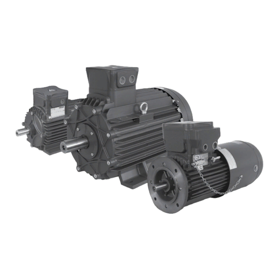

Summary of Contents for cemp DB 30
- Page 1 Electric Motors with brake Additional use and maintenance instructions Industrieweg 16 NL-3881 LB Putten T +31 (0) 341- 36 96 96 F +31 (0) 341- 36 96 90 E info@kolmer.nl...
-
Page 2: Table Of Contents
CONTENTS Page General information ... . . 20 Description of the product ..21 General operation ....21 Construction method for the brake motors sizes 71÷160 . -
Page 3: General Information
Motor type Version Ex d IIB Ex de IIB Ex d IIC Ex de IIC Three-phase, 1-speed (2, 4, 6, 8 poles) unventilated or DB 30 DB 35 DC 30 DC 35 forced ventilation Single speed, three-phase, HB 30 HB 35... -
Page 4: Description Of The Product
2. Description of the The brake holder shield shuts off the motor enclosure and allows the shaft to pass through it product In the case of self-ventilated motors (H Series) the shaft protrudes from the brake cover enclosure through a flameproof joint. A fan is applied to the 2.1 General operation protruding part of the shaft The brake enclosure and the fan are protected by the... - Page 5 ctdq dm dl dp Series D 63÷160 ctdq dm dl dp dt cr bq Series H 71÷160 Fig. 2A...
- Page 6 Series D 180÷315 dt dm Non-ventilated dl dp ct dt bq cr Servo-ventilated dqdl dp Fig. 2B...
-
Page 7: Construction Method For The Brake Motors Sizes 71÷160
2.2 Construction method for the 2.3 Construction method for the brake motor sizes 71÷160 brake motor size 63 A pinion (toothed hub) is coupled to the motor A pinion (toothed hub) is coupled to the motor shaft . The brake disc is fitted on the toothed shaft . -
Page 8: Construction Method For The Brake Motors Sizes 180÷315
2.4 Construction method for the 2.5 Manual release 71÷160 brake motor sizes 180÷315 (optional on request) Size 71÷160 motors can be fitted with a manual The braking unit is secured to the brake holder shield brake release lever that allows the shaft to rotate with eight fixing screws even when the power is off. -
Page 9: Manual Release 180÷315 (Optional On Request)
AC400V/3 20Nm IC416 Ta40° C J = 0.283 kgm kg 52 Manufacturer Cemp srl - I 20030 SENAGO (Milan) - ITALY regrease joints after any dismounting - fasteners quality 8.8 EN 898-1 Brake Brake for motors 63÷160 Figure 3A - Fig. -
Page 10: Electrical Connections
3.4 Manual release (optional on 3.2 Electrical connections request) Before making the connection check When the motor is fitted with a manual brake release the data shown on the nameplate against that on lever it must be installed so as to avoid any acciden- the connection diagram. -
Page 11: Maintenance
4. Maintenance • Check that the friction surfaces (brake disc, brake holder shield, and mobile armature) are clean and free from oil or grease. 4.1 Introduction 4.3 Adjusting the braking torque Any work on the motor is to be carried motors 63÷160 out with the machine stopped and disconnected from the power supply. -
Page 12: Adjusting The Air Gap Motors 63÷160
Table 4A - Adjusting the braking torque Braking torque [Nm] for A = Frame Brake size type [mm] +1mm A +2mm A +3mm A +4mm A +5mm A +6mm MEC 63 17,0 13,5 10,0 MEC80 35,0 32,0 29,5 27,0 24,0 21,5 18,5 MEC90(... -
Page 13: Changing The Brake Disc Motors 63÷160
For size 63 motors (fig. 4B), proceed as follows: 4.5 Changing the brake disc - Unscrew the fixing screws and remove the sin- motors 63÷160 gle unit being careful not to damage the power supply cable for the brake. Pull the brake disc off The brake disc must be changed when 1,5 mm of the toothed hub. -
Page 14: Adjusting The Braking Torque And Replacing The Braking Unit And/Or Its Parts For Motors 180÷315
4.6 Adjusting the braking torque and Size replacing the braking unit and/or 180÷315 its parts for motors 180÷315 To replace the braking unit or one of its parts (elec- tro-magnet , mobile armature , brake disc springs , it is necessary to remove both the brake enclosure shield and the brake cover enclosure A) Disassembly of the brake enclosure shield... -
Page 15: Adjusting The Air Gap Of
G) Final reassembly f2) To replace the microswitch , first remove the Remount the brake cover enclosure and the brake eight screws and the brake enclosure shield cover with the relative fixing screws, taking care to taking care not to damage the coupling joints. grease the coupling joints lightly beforehand. -
Page 16: Troubleshooting
5. Troubleshooting Fault Possible causes Solution The brake does not release Air gap too big (wear) Check the air gap. Replace the brake disc if necessary No power to the brake Check electrical connection Low power supply voltage for the Check power supply voltage brake Brake disc stuck mechanically... - Page 17 Due to Cemp s policy of con- Tuttavia, anche in conse- tinuous development and Néanmoins, compte tenu de In keinem Fall können jedoch No obstante, como consecuen-...
- Page 18 Industrieweg 16 NL-3881 LB Putten T +31 (0) 341- 36 96 96 F +31 (0) 341- 36 96 90 E info@kolmer.nl...