Table of Contents
Advertisement
Quick Links
Advertisement
Table of Contents

Summary of Contents for Franklin Electric CELLGUARD
- Page 1 CELLGUARD ™ wired Battery monitoring system Installation guide...
- Page 2 Copyright © 2020 Franklin Electric Co., Inc., Madison, WI 53718. All world rights reserved. No part of this publication may be stored in a retrieval system, transmitted, or reproduced in any way, including, but not limited to, photocopy, photograph, magnetic, or other record, without the prior written permission of Franklin Electric Co., Inc.
-
Page 3: Table Of Contents
Contents Introduction ............................1 System components ........................2 Accessories ..........................4 Battery sensor components .......................5 String sensor components ......................5 The BC ............................6 Specific functions ........................6 Components ..........................7 Indicator lighs ..........................7 Installation............................9 Assembly ............................9 Numbering batteries ........................9 Addressing .............................11 Installing sensor cables .......................12 Crimping sensor cables .......................12 Addressing sensors ........................13 Addressing the TC ........................14 Connecting the BC and TC ......................15... - Page 4 Configuring network connections ....................26 Performing the Resistance Test ....................28 Confirming IR values ........................28 Configuring the Franklin Interface (FI) ..................29 Starting the FI ..........................30 Commissioning the site .........................32 Setting up batteries ........................33 Setting alert limits ..........................35 Setting discharge limits .......................35 Testing and confirming communication ..................36 Editing IP address names .......................37...
-
Page 5: Introduction
Introduction Franklin Electric Grid Solutions Wired Battery Monitoring System (BMS) consists of battery sensors (TA) that measure voltage, temperature, and the internal resistance of the battery. TC sensors measure the battery string current and ambient temperature. Both sensors report data to the Base Controller (BC) module: •... -
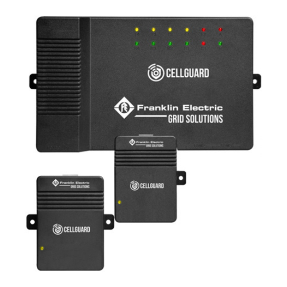
Page 6: System Components
System components 1. BC. 2. Battery sensor module. 3. String sensor module. 4. Current transducer. 5. Celltraq™ data management software. - Page 7 • The TAs collect the voltage, internal resistance, and temperature of each cell. • The TC collects the ambient temperature and the charge and discharge current of battery strings. • All sensors and TCs are connected though a UART bus, back to the BC. •...
-
Page 8: Accessories
Accessories • Battery tabs (acquisition terminal). • The Address Modifier-HA-6224AAAO is used to address TAs and TCs: • The Interconnect cable is used to connect TAs and TCs to the BC and is included with sensors: 13" and TC -8 m (25"). •... -
Page 9: Battery Sensor Components
Battery sensor components 1. Indicator light. 2. Battery connection port. 3. COM port. String sensor components 1. Indicator light. 2. Battery sensor connection port. 3. COM port. 4. Power input. -
Page 10: The Bc
The BC The BC can read the monitoring values, one-by-one, from TAs and TCs. This includes: • Analysis and processing of data received from TAs and TCs. • A maximum of six battery strings for each BC and 2 strings per COM port. Specific functions The BC reads each sensor in series to the end strings or strings including a TC. -
Page 11: Components
Components 1. Alarm indicator lights. 2. Power input. 3. Power output. 4. Dry contact. 5. Upload port. 6. LAN port. 7. Communication ports. Indicator lighs • P–Power light. • A–Alarm light. • E1–Commuincation failure. • E2–Battery alarm. • R1/T1–Transmit and receive for COM1. •... - Page 12 Intentionally Blank...
-
Page 13: Installation
Installation Assembly Numbering batteries Before you connect the TAs to the batteries, label and number both the TAs and batteries clearly. • The first battery, or battery NO.1, must be the first one on the string's positive terminal, the NO.2 is the battery following the NO.1 battery, and so on: •... -
Page 15: Addressing
Addressing Install the U-type acquisition terminals (provided) on each post on top of the batteries to be monitored. Install the terminals in the following order: U-type acquisition terminals > Flat washer > Spring washer > Nut (or bolt) Battery connector Flat washer Spring washer U-type acquisition terminal... -
Page 16: Installing Sensor Cables
Installing sensor cables Attach the appropriate end of the sensor cable to the tabs on the U-type acquisition terminal, and then plug the sensor cable into the sensor module connector. Crimping sensor cables IMPORTANT: You must use an RJ-22 crimping tool. -
Page 17: Addressing Sensors
Addressing sensors Power light COM1 1. Make sure the sensor is secured on the batteries, and confirm the power light in the lower left corner is green. 2. Use the TA address modifier (provided) to: • Connect the connector wire to the TA address modifier and COM1 of the sensor. •... -
Page 18: Addressing The Tc
Addressing the TC The default TC address is 241, but you can choose an address from 241 to 247. If you are monitoring only one battery string, the address can remain the default. To change the address: 1. Connect the address modifier to COM1 on the TC. 2. -
Page 19: Connecting The Bc And Tc
Connecting the BC and TC The BC • COM1 on the BC: • Left side to either COM port on the TC. • Right side from COM2 of the last battery in string 1 or string 2, if you use two strings for each COM port. -
Page 20: Wiring The Ta
Wiring the TA TA 1 • COM1 and COM2 act identically once they are addressed. • The last sensor in the string, COM2, has a home run back to the right port on COM1 on the Last sensor in string... -
Page 21: Wiring Multiple String Sensors In Series
Wiring multiple string sensors in series NOTE: This wiring method uses the same COM port. Wiring multiple string sensors in parallel NOTE: This wiring method uses multiple COM ports. -
Page 22: Wiring The Bc And Tc
Wiring the BC and TC The TC • TC (8-13VDC- 1W-from the BC): • Wire (18-22AWG). • Red (+) on left. • Black (-) on right. The BC IMPORTANT: These terminals are at the far end of the terminal strip, to the left of J1. •... -
Page 23: Connecting The Current Transducer
Connecting the current transducer Use the provided cable to connect to the TC: • A 4-pin terminal connects to the current transducer. • A white, six-section plug connects to the top of TC. • You can separate the current transducer, which should be embedded in the cable of the positive pole of the battery string and fastened with a cable tie. -
Page 24: Powering The Bc
Powering the BC 48VDC parasitic option: • Connect the power cable to both the positive and negative ends of the string: • Connect the positive end of the string to the most positive battery in the string. • Connect the negative end of the string to the most negative battery in the string. •... -
Page 25: Commissioning The Bc
Commissioning the BC Connecting the BC web interface 1. Update the connection properties in order to connect directly to the BC using an Ethernet(RJ-45) Cat 5-6 cable. Right click Ethernet>Properties 2. In the Ethernet Properties window, select Internet Protocol Version 4 (TCP/IP) Properties, and enter IP Address 192.168.0.1 (the default the gateway of the unit). -
Page 26: Using The Integrator Tool
Using the Integrator tool 1. Make sure the unt is connected with an Ethernet cable, and open the Integrator tool. 2. Set IP Address to 192.168.0.105 and Port to 4007. 3. Click OFF to turn on–connect. 4. String 1 appears once connected. -
Page 27: Setting Up String Parameters
Setting up string parameters 1. Click Parameters, and open Easy Setup. 2. Choose the string number you want to configure. 3. Choose the battery voltage. 4. Choose the number of cells in the string. 5. Set the capacity (Amp hours), and then click Apply. Changing port settings 1. - Page 28 3. Change port numbers as follows: NOTE: The field to right is an editable field. The icon to the left changes to once a change is made. 4. Once all settings are edited, click Write. The following message appears when all parameters have been changed:...
-
Page 29: Changing Ir Settings
Changing IR settings Parameters string information: 1. Make sure Correction and Slope Correction are set to 1000. 2. To correct, enter 1 in each field for the correction and slope correction. 3. Click Write. 4. Click Read to confirm the change. -
Page 30: Connecting The Bc Web Interface
Connecting the BC web interface 1. Make sure the unit is connected with an Ethernet cable, and then open a browser. 2. Enter IP address 192.168.0.105. 3. Enter “2022” in Password. Configuring network connections The following is the Menu tab on the web Interface landing page:... - Page 31 1. Choose System Parameters on the web Interface landing page Menu tab. 2. Enter the appropriate network information (as shown below), and then click Modify. 3. Choose System Maintain on the web Interface landing page Menu tab, and then click Reset. NOTE: After you complete a change, you will need to update the laptop connection parameters to reconnect to the BC.
-
Page 32: Performing The Resistance Test
Performing the Resistance Test The Resistance Test screen allows you to run an internal resistance test on all sensors. You must complete this test at commissioning. 1. Choose Resistance Test on the web Interface landing page Menu tab. 2. Select the string to be tested, and click Test IR. During the test, each sensor light turns red. 3. -
Page 33: Configuring The Franklin Interface (Fi)
Configuring the Franklin Interface (FI) NOTE: The following files and programs are in the .zip file provided by Franklin Electric. IMPORTANT: Configure the FI before you open it. 1. Open the certificate file with Notepad. You must restart the FI to make further changes. -
Page 34: Starting The Fi
Starting the FI 1. Right click Franklin Interface and choose Run as Administrator. The Franklin directory appears. NOTE: The Commission Site button remians grayed out until the site parameters are complete. 2. Right click the directory FRANKLIN. Add the BC site IP address. - Page 35 3. Right Click Site>Add Plant. 4. Right click Plant to add strings. Click Plant again to add additional strings.
-
Page 36: Commissioning The Site
Commissioning the site The Commission Site button should be active. 1. Click Commission Site. 2. Login to Celltraq™ to confirm the Celltraq™ heirarchy is populated. 3. When you have confirmed the Celltraq™ heirarchy is populated, update the certificate file as follows •... -
Page 37: Setting Up Batteries
Setting up batteries 1. Log in to Celltraq™, click Config, and expand the hierarchy to the string level. 2. Choose Edit to open the Edit String screen. 3. Confirm the Battery Type is correct. If so, the proc edure is finished. If not, got to the next step. - Page 38 5. Select Manufacturer to access information about the battery model. You cannot enter battery specifications if the correct model is not listed. 6. Click the model number of the battery for which you want to enter specifications. 7. If alarms or measurements exist for previous batteries, clear them by choosing Clear Aalarms and then deleting the measurement history.
-
Page 39: Setting Alert Limits
Setting alert limits 1. Click Config and then Alert Limits. 2. Set parameters for the string and battery alert limits. To correct alert limits, click Edit to change measurements. 3. Click Save when completed. To edit additional measurements, repeat the previous step. Setting discharge limits •... -
Page 40: Testing And Confirming Communication
Testing and confirming communication 1. Change the times in the certificate file to 2. Thi sets 2-minute intervals. 2. Open the FI, and confirm that scanning is active. Stop Scan is the only selection under Setting. 3. Choose Debug. The screen slowly populates. 4. -
Page 41: Editing Ip Address Names
Editing IP address names When the site is active and sending data to Celltraq™, you can modify the IP address to better resemble the site name. 1. Click Config. 2. Click the site. 3. Click Overview. 4. Click Edit. Change the Name field to the name you prefer for the site. 5. - Page 42 Intentionally Blank...
- Page 43 Intentionally Blank...
- Page 44 167-000800 r1...
Need help?
Do you have a question about the CELLGUARD and is the answer not in the manual?
Questions and answers