
Summary of Contents for Marley LLC+u
- Page 1 LLC+u ultrasonic water level control I N S TA L L AT I O N - O P E R AT I O N - M A I N T E N A N C E...
-
Page 2: Table Of Contents
This manual contains vital information for the proper installation Note and operation of the LLC+u controls. Carefully read the manual be- fore installation or operation and follow all instructions. Save this manual for future reference. System Diagram ......................4 Description ........................4 Programming ........................6... - Page 3 Safety First The Marley control system uses UL listed components installed in accordance with the National Electric Code. The location of the cooling tower and field installation of the control system can affect the safety of those responsible for installing, operating or maintaining the tower and controls.
-
Page 4: System Diagram
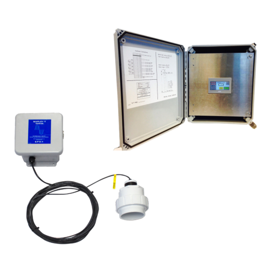
SYSTEM DIAGRAM Optional Field Components—by others LLC Components 30'-0 Lead 4-20mA level signal Pump Sensor High and low alarm dry contacts High and low cut-off dry contacts LLC+u Junction Control Panel Pump with Display MU powered with 120V Display Solenoid Ethernet... - Page 5 description Route incoming power cable from the bottom of the enclosure up into the top (line) side of the main circuit breaker. Circuit breaker powers a remote solenoid. H-O-A selector switch for makeup solenoid circuit. If a makeup solenoid circuit is provided, connect the solenoid wires here at points 4A and 2A.
-
Page 6: Programming
programming SCREEN LAYOUT Red indicates the relay inside the control panel has been energized. LEVEL IN INCHES–actual water level in the cold water basin GO TO SETUP–use to program sensor heights and setpoint levels. Default password is 1492 INFO–use to see programmed levels Requires field programming Note 1. - Page 7 programming CIRCUIT PROTECTION Main circuit breaker powers the control panel Feeder breaker powers the remote solenoid. PROGRAMMING STEPS Power ON the control panel circuits by moving the switches on the two circuit 1" breakers to the up position. BOTTOM OF SENSOR Measure the distance from the bottom of TO BASIN FLOOR the ultrasonic sensor to the basin floor.
- Page 8 ENT to save. Recommended levels are unique for every cooling tower and are available from your Marley sales representative. When finished press GO TO MAIN to return to main screen. On the main screen are view actual water level and relay actions. The reac- tion time is purposely slow to allow time for the system to react and refresh the screens.
-
Page 9: Operation
A 4-20mA output is provided for BMS remote monitoring of water level Water Makeup Function The circuitry for water makeup in the LLC+u control panel provides an inde- pendent circuit breaker for direct connection to a 110-120VAC water solenoid valve. This added feature allows customer installation without having to provide an additional power circuit to energize the solenoid. -
Page 10: Troubleshooting
troubleshooting The control panel has been factory tested before shipment and most issues lie outside of the control panel e.g. proper field wiring connections to the control panel. In an effort to troubleshoot the system, please check the following: • The two circuit breakers must be energized with operating handles in the up position •... -
Page 11: Field Wiring - Parts List
• Red to terminal point +24 • Black to terminal point 13 • Shield to GND (Do not ground shield any other location, only at the LLC+u control panel) • The white and green sensor wires are not used. Wire 4-20mA output signal representing the water level in basin from points 4-20+ and 4-20- to customers BMS system. - Page 12 LLC+u water level control U S E R M A N UA L SPX COOLING TECHNOLOGIES, INC. 7401 WEST 129 STREET Z1079969 ISSUED 10/2018 OVERLAND PARK, KS 66213 USA ©2018 SPX COOLING TECHNOLOGIES ALL RIGHTS RESERVED 913 664 7400 | spxcooling@spx.com In the interest of technological progress, all products are subject to design spxcooling.com...
Need help?
Do you have a question about the LLC+u and is the answer not in the manual?
Questions and answers