Advertisement
Quick Links
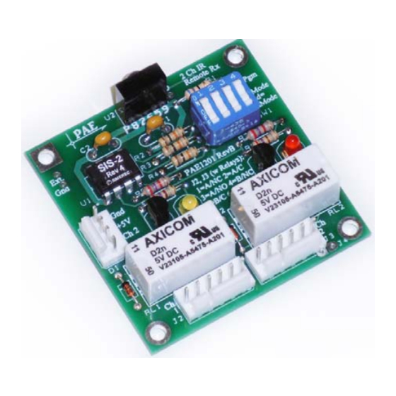
Universal IR Remote Receiver, 2 Channel ― JAMECO PART NO.
This is an infrared remote receiver module that is designed to work with the majority of existing
infrared remote controls to allow the operation of your devices with these controls. It provides two
control channels with two state outputs (on/off) that can be configured in a number of ways: see
characteristics below.
Characteristics:
Operates with IR signals from 99% of existing IR remotes (TV, VCR, cable, DVD, etc.)
"Learns" remote code from the chosen remote transmitter – no programming (computer code) required
Non-volatile, reprogrammable memory
Momentary, sustained/toggle, or definite action outputs
Logic, transistor (open collector or with pull up), or relay (DPDT) outputs
5 Volt DC operation, low quiescent current
Easy Assembly – no surface mount components
Required tools and parts:
Soldering iron and solder
Small diagonal cutters
Small needle nose pliers
Sponge or scrap of packaging foam
Kit Includes:
2171604
Experience Level: Beginner | Time Required: 30-60 Minutes
Advertisement

Summary of Contents for Jameco Electronics 2171604
- Page 1 Universal IR Remote Receiver, 2 Channel ― JAMECO PART NO. 2171604 Experience Level: Beginner | Time Required: 30-60 Minutes This is an infrared remote receiver module that is designed to work with the majority of existing infrared remote controls to allow the operation of your devices with these controls. It provides two control channels with two state outputs (on/off) that can be configured in a number of ways: see characteristics below.
- Page 2 Part No. Qty. Description 25523 Capacitor,0.1µF 36038 Diode 232303 Header 232282 Header 38360 Transistor 690582 Resistor,68 Ω 690726 Resistor,270 Ω 690961 Resistor,2.7 KΩ 2081932 LED, Orange Red diffused 696888 Switch 34657 LED, Yellow diffused 2157167 Resistor,10 KΩ Instructions Insert R1, R2, R3, and R4. Solder at 8 places. Step 1 –...
- Page 3 Step 3 – Insert R5, R6, R7, and R8. Solder at 8 places. Insert C1 and C2. Solder at 4 places Step 4 –...
- Page 4 Insert Q1 and Q2. Note the correct orientation (flat side). Solder at 6 places Step 5 – Insert S1. Note the correct orientation. Solder at 8 places. Step 6 -...
- Page 5 LED1 (yellow) and LED2 (red). Note the correct orientation (flat side). Solder at 4 places Step 7 - Insert Insert U2 (TSOP1138). Note the correct orientation. Also notice that there are extra solder pads in this Step 8 - location to allow other IR receiver ICs to be used.
-
Page 6: Assembly Options
Insert J1. Note the correct orientation. Solder at 4 places. Step 9 - Assembly Options: Option 1. If only logic outputs are desired, the board is now complete. Do not perform Option 2 or 3. Option 2. If relay outputs are desired, complete the following: Insert D1 and D2. - Page 7 Insert J2. See the instruction for J1, above for the correct orientation. Solder at 6 places. Insert RL1 and RL2. Note that the relays can only be inserted in one orientation. Solder at 16 places. ...
-
Page 8: Operation
Insert J3. See the instruction for J1, above for the correct orientation. Solder at 6 places. (see photo above) If relay outputs are desired, the assembly is now complete. Do not perform Option 3. Option 3. If transistor outputs are desired, complete the following: Short J4, J5, and J6 with solder bridges or wire jumpers. - Page 9 External Connections: J1, J2, and J3 are Molex header connectors with standard 0.025” square pins and a 0.1” pin-to-pin spacing. This style is extremely common and a large number of mating, female connectors with different termination styles are available. These styles include solder, crimp, and insulation displacement termination.
- Page 10 The outputs can be configured for several types of action. This configuration is made with sections “c” and “d” of the DIP switch, SW1. The available choices are as follows: SW1-c SW1-d Operation Momentary Toggle Definite this state is not defined and should not be used Momentary action will activate the outputs while the code is being received (while the remote button is being pressed) and deactivate them when the code is no longer being received.
Need help?
Do you have a question about the 2171604 and is the answer not in the manual?
Questions and answers