
Related Manuals for Daking Audio FET III

Summary of Contents for Daking Audio FET III
- Page 1 Daking Audio FET III Stereo Compressor/Limiter Manual VERSION 1.4 Hendrik David Gideonse XIX 3/26/2010...
- Page 2 Safety Considerations 1. Read, follow and keep these instructions. 2. Heed all warnings. 3. Do not use this equipment in or near water. Do not place liquids on or near the device because the device might be damaged during a spill. 4.
-
Page 3: Table Of Contents
Line Output (XLR) ..................15 1.5.4 +48V DC with a 6 pin DIN connector ............15 Signal Flow: Patching Into and Out of Your FET III Compressor ....15 1.6.1 Mic Pre to FET III to Audio Interface or Mixer ......... 15 1.6.2... - Page 4 1.7.5 Limiting to preventing overload, clipping and distortion ......21 1.7.6 Pointers and General Principles ..............22 Specifications ..................... 23...
-
Page 5: Daking Audio Fet Iii Stereo Compressor/Limiter Manual
1.1 About Daking Audio Congratulations! You‟ve purchased a FET III Stereo Compressor/Limiter, a very high end piece of gear! The FET III uses all discrete transistor Class A circuits, THAT Corporation differential amps and printed circuit board mounted switches. Signal capacitors are precision polypropylene or ultra low- leakage electrolytic types. -
Page 6: Basic Set Up
1.2.2 Basic Set Up Your compressor can be used in a variety of different ways and patched into the signal chain of many different set-ups. The FET III can be used while you are tracking a microphone, while you are mixing tracks down, and in mastering scenarios. - Page 7 Figure 1 FET III Block Diagram...
-
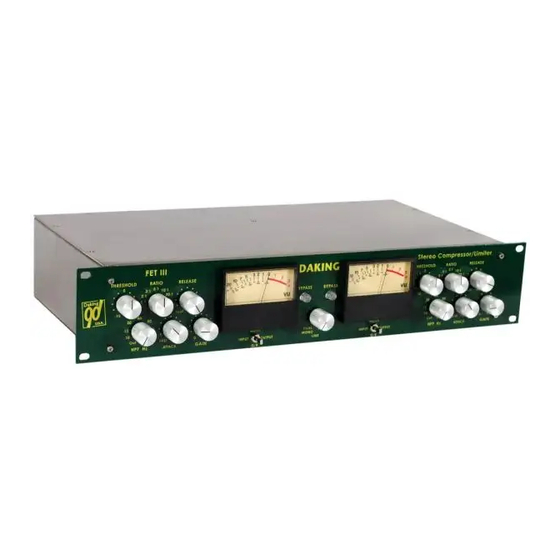
Page 8: Front Panel
The FET III uses switches on the Ratio control so that it is easy to use the exact same ratio on both the left and right side of the compressor. - Page 9 Limiters can also be used to set a volume limit for a playback system to protect speakers from damage. Figure 2 Threshold and Ratio Settings with Meter Readings...
-
Page 10: Attack Knob (From 250 Μs To 64 Ms)
Audio & Design (Recording) Limited‟s famous F760X 'Compex' limiter. When the FET III is in full Auto mode, the release starts out pretty fast, but then slows down. The total release time can be as long as 7-8 seconds, but dual... - Page 11 Figure 3 Attack and Release Times...
-
Page 12: Hpf (High Pass Filter: From Off To 200 Hz)
This feature is especially useful when you are using the FET III for stereo buss compression. As you turn up the HPF knob, you will notice that it has the effect of boosting the bass frequencies, while the mids and upper frequencies get more controlled. -
Page 13: 3-Way Meter Switch
sound wave. This is really important for digital because anything that goes above 0 dB full scale is going to distort and sound horrible. The meter can also be used to determine gain reduction in addition to input and output levels. When the compressor is working, the needle will move to the left to show how much the compressor is attenuating (reducing) the gain. -
Page 14: Back Panel
Back Panel 1.5.1 In General: XLR Connectors XLR connectors are more expensive, more reliable and offer a stronger connection than ¼” TRS connectors. They also have the option of a locking latch that helps to keep the cable from being pulled out accidentally. -
Page 15: Line Output (Xlr)
1.5.4 +48V DC with a 6 pin DIN connector Your FET III Compressor uses an +48V DC external power supply with a DIN connector that is very similar to a laptop power supply. External... -
Page 16: Connecting Via A Single Insert Jack
(XLR Female to XLR Male). 2. Patch out of the mic preamp to an input jack on the FET III, with another mic cable (XLR Female to XLR Male). - Page 17 Figure 6 Insert Cable for Use with FET III On the familiar RCA plugs used on home theater equipment, the red plug is always the right side. „Y‟ cables often use the same color scheme because usually the cable was intended to split a stereo signal into two mono signals: left and right.
-
Page 18: Via A Patch Bay
1. Patch from the bottom back jack on the patch bay module to the input on the FET III using the ¼” TRS to XLR Male cable. 2. Patch to top jack of the patch bay module from the output of the FET III using the XLR Female to ¼”... -
Page 19: Stereo Setup As A Bus Compressor For Mixing Or Mastering
Steps: 1. Connect both sides of the FET III to the left and right sides of the program respectively. Insert the... -
Page 20: Typical Uses Of A Compressor
2. Set the Ratio, Attack and Release to the same setting on both sides and then adjust the Threshold controls so that both sides are showing equal Gain Reduction and equal Output levels. 3. Return your bus back into stereo and both sides will be balanced equally. -
Page 21: Keeping Bass Consistent
1.7.3 Keeping bass consistent A compressor is a great tool to use to smooth out a bass guitar track and help to keep the bass audible during the louder parts of the mix. The bottom end of the band is very important! Bass guitar has a tremendous amount of energy and readily overloads tracks. - Page 22 overload (saturation) from too high an input. Using a very fast Attack time and a high Ratio will ensure that the fastest transients are captured. A good starting point for limiting is: Parameter Value Threshold +10 Ratio 20:1 Attack 250 µs Release .5 Make-up Gain 0 1.7.6 Pointers and General Principles...
- Page 23 Specifications Method of Limiting: FET (Field Effect Transistor) used as a variable resistor Stereo Linking Method: Continuously Variable Audio Summing Power: 48volts dc @ 150 ma Output Drive: Differentially balanced +24dbv @ 1kHz 600 Ω Ratios: 1.5:1, 2:1, 3:1, 5:1, 10:1, 20:1 Attack Times: 250 μs to 64 ms Release Times: 500 ms to Auto Dual Time Constant Frequency Response: ±1db 10Hz to 56kHz 3db down 63kHz...
Need help?
Do you have a question about the FET III and is the answer not in the manual?
Questions and answers