Advertisement
The OxyScan Transmitter is a measuring amplifier for UMS oxygen sensors
to measure dissolved oxygen in liquids.
The liquid temperature and the atmospheric pressure are measured
simultaneously and automatically compensated.
The measured value is output as a current signal via a 4-20 mA current
loop. There is no need for additional electric power.
Handling of the O2 sensor (electrochemical)
Always store the sensor in its calibration chamber when not in use!
The membrane (thin, be careful) atthe sensor tip can be cleaned carefully
with a moistened cotton ball.
A constantly increasing display value indicates a damaged membrane.
In this case, the sensor must be replaced or regenerated.
The sensor consumes minimal amounts of O2 during the measurement.
Therefore it requires a little liquid flow to achieve stable readings.
For measurements in standing liquids, the sensor should be moved
slightly.
For permanent installation in piping systems:
The liquid flow rate should be at least 2 cm / sec.
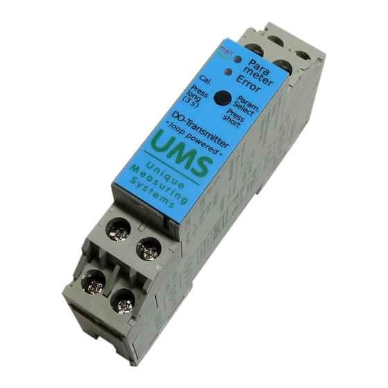
Operation manual
OxyScan Transmitter DIN rail
1
Advertisement
Table of Contents

Related Manuals for UMS OxyScan Transmitter DIN rail

Summary of Contents for UMS OxyScan Transmitter DIN rail
- Page 1 Operation manual OxyScan Transmitter DIN rail The OxyScan Transmitter is a measuring amplifier for UMS oxygen sensors to measure dissolved oxygen in liquids. The liquid temperature and the atmospheric pressure are measured simultaneously and automatically compensated. The measured value is output as a current signal via a 4-20 mA current loop.
- Page 2 The sensor may be mounted vertically to horizontally, but the sensor tip must not be higher than the sensor end! ommissioning The UMS oxygen sensor is connected to the lower terminals: White Blue NTC1: Black + Yellow/Green NTC2: Brown Power is supplied through the current loop at the upper terminals (+ / -).
- Page 3 In case the transmitter is connected to a 20 mA input with power supply, only the two lower terminals ("+" and "-") have to be connected: UMS Transmitter 20 mA Input „Loop(+)“, respectively LOOP BLUE „Loop(-)“, respectively LOOP RET The two middle clamps are connected together.
- Page 4 The output of the oxygen value can be either absolute (mg / l) or relative to the saturation concentration (% sat). To switch the output mode, press the button on the transmitter briefly (about 1 s). Conversion of the measured values: Abslute value: (Iout –...
- Page 5 Calibration During calibration, the sensor must be inserted in the supplied calibration chamber. In this there is a sponge, which should be kept moist. The sensor should be powered for at least 5 minutes before calibration. (in case of a new or recently regenerated sensor, or if the sensor has not been used for more than 2 weeks, 10-15 minutes are recommended) During this time and during calibration, the sensor must be in the supplied calibration chamber!
- Page 6 Technical specifications: Input UMS oxygen sensor Output Dissolved oxygen concentration, optionally mg/l or %saturation Normal 4..20 mA Alarm signal: 24 mA Power supply 6-32 VDC, min. 24 mA Storage and operating 0 .. 70 °C temperature of the sensor Measuring ranges:...
- Page 7 We provide a 12-month legal guarantee on the entire measuring system. In the guarantee case, please return the sensor or measuring instrument with the test certificate. UMS GmbH & Co. KG Oberdorfstr. 19 97647 Willmars, Germany Tel. +49 (0) 9779 850343 Fax +49 (0) 9779 850344 info@ums-gmbh.de...
Need help?
Do you have a question about the OxyScan Transmitter DIN rail and is the answer not in the manual?
Questions and answers