Table of Contents
Advertisement
Quick Links
Advertisement
Table of Contents

Subscribe to Our Youtube Channel
Related Manuals for Industrial Music Electronics BIONIC LESTER MARK III

Summary of Contents for Industrial Music Electronics BIONIC LESTER MARK III
- Page 1 BIONIC LESTER MARK III OPERATIONS MANUAL • FIRMWARE V1.1...
-
Page 2: Getting Started
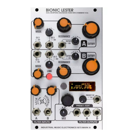
FUNDAMENTALS BIONIC LESTER is a dual digital filter with a digital overdrive VCA. The voltage-controlled filter is a fundamental component of modular sound synthesis that modifies the spectrum of an audio signal. Bionic Lester excels at classic subtractive lowpass filter effects, as well as multimode operation and advanced short delay lines with the allpass/ comb filter modes. Each Bionic Lester filter section is a 2-pole (-12db per octave) state-variable filter with smoothly morphable mode. The filter does not self-oscillate, though in the comb filter mode it will sustain the harmonic peaks without clipping. GETTING STARTED Patch your input signal to the FILTER A input, and listen to the signal coming out of the FILTER A output.. Turn the A GAIN control up halfway. Turn the FILTER A resonance and Mode control sfully counterclockwise (low pass mode). Turn the large FILTER A cutoff knob and listen to the effect on the sound. Next, move Filter A's Resonance control and move the cutoff knob again. The Resonance control emphasizes the frequencies around the cutoff. You will now hear that emphasized "peak" frequency move throughout the input sound's spectrum as you move the cutoff. GAIN CONTROL The input stage of the filter passes through a special digital VCA that can introduce subtle overdrive and clipping to a signal before it gets filtered. When the control is fully counterclockwise, the signal is fully attenuated. When the control is towards its middle position, the attenuation decreases until the signal is at its full input volume. When you turn the control past the center position, soft clipping will be introduced onto the signal. At the extreme end of the control, the signal will clip harder. NOTE: The clipping element of the input VCA expects oscillator-level signals in the range of 10 volts peak-peak for best results. NOTE: When the clipping element is active, the filter’s name on the display (A or B) will be displayed with an inverted color scheme (black letter on orange background). MODE CONTROL Voltage-controlled multimode filters traditionally feature an array of signal outputs representing each filter mode. Bionic Lester has a smooth Mode crossfade control that feeds one output per filter. When it is turned to the extreme counterclockwise position, the filter is in Low Pass mode. As the control is turned clockwise, the filter output fades its mode from one to the next. The control's position relative to each filter mode is shown on the OLED display. MODE RESONANCE CUTOFF CV input 3 CV input 2 CV input 1... - Page 3 LOW PASS Frequencies ABOVE the cutoff frequency are attenuated. The resonance control emphasizes the frequencies near the cutoff. LOW PAss frequency BAND PASS Frequencies ABOVE or BELOW the cutoff frequency are attenuated. The Resonance control emphasizes the frequencies near the cutoff and steepens the “slope” of the cutoff. bAND PAss frequency HIGH PAss Frequencies BELOW the cutoff frequency are attenuated. The resonance control emphasizes the frequencies near the cutoff. frequency HIGH PAss BAND REjECT (NOTCh) Frequencies near the cutoff frequency are attenuated in a "notch" pattern. The resonance control causes the notch to become narrower and steeper. frequency bAND REjECT ALL PAss/COmb When the MODE control is turned fully clockwise, the cutoff frequency display will change to show the length of the allpass/comb delay line. In this mode, the filter functions as an all-pass filter when the Resonance control is at zero (all frequencies are passed with no change in amplitude, but with a change in phase) As you turn the resonance control towards the center position, the filter type changes to a positive feedback comb (which introduces equally spaced peaks into the spectrum frequency POSITIVE COMb of the signal), with increasing feedback. The cutoff control changes the spacing of the peaks.
-
Page 4: Screen Saver
SCREEN SAVER The Bionic Lester’s display is an OLED. It is set to a brightness to provide the best balance between visibility and long life. To preserve the life and maximum brightness of the OLED, it will turn off if a button or encoder is not used for 10 minutes. To turn it back on, press a button or turn the encoder. mK III mENU sYsTEm Most function blocks in Industrial Music Electronics modules have hidden menus associated with them. To access them, hold down the rotary encoder button and push the associated button. The menu will appear on the display. Turn the encoder to select the desired menu item. Push the encoder to select the item, and turn the encoder to change the selected item. Push the encoder button again to enter your selection. Exit the menu by pressing any of the other buttons. If a button does not have a menu associated with it, then the button press combination will usually invoke another shortcut function. CV INPUTS Each filter section has three control voltage inputs, known as CV1, CV2, and CV3. These inputs are used with external control voltages to remotely modify the synthesis parameters faster than your hands can turn the related controls. CV1 is always assigned to the filter’s cutoff frequency, and has an associated attenuverter. The other two inputs can be freely assigned to its filter’s cutoff, gain, resonance, or mode. To access the assignment menu, hold down the black rotary encoder button and press the LINK button. You can now use the encoder to select and edit each of the four assignable CV inputs. To leave the menu, press LINK again. All CV inputs on the Bionic Lester accept full-scale, bipolar control voltages with a range of +/-10v. The response of the various inputs are scaled to provide a musically useful range of motion within the typical range of +/-5V, with additional reactivity far outside Turn Turn CLOCKWISE to ADD CV to parameter COUNTER- of this range. The attenuverters use a nonlinear CLOCKWISE curve to allow a typical control voltage to subtly to SUBTRACT CV Input modulate a small range of the parameter, or full-swing travel without the use of external amplification. -
Page 5: Preset Manager
sERIEs The signal at the Filter B input jack will be ignored. The output of Filter A is internally routed to the Filter B input, with all controls remaining independent. To hear the combined effect of the series processing, listen to the Filter B output. This mode is useful for finely tuning the response of a dual filter arrangement with precise management of the distortion products. 4POLE The 4POLE mode is identical to the SERIES routing, but all control settings from Filter A will be copied to Filter B. Patch your input signal into Filter A input and listen to the Filter B output. The slope, distortion, and resonance of the filter will be more intense. You can hear the normal 2-pole output of the filter by listening to the Filter A input. The MIX output has a 3-pole output when the knob is in the center position. sTEREO: The STEREO mode has independent inputs and outputs, but the controls from Filter A are copied to Filter B. This mode is meant to be heard with a stereo signal patched into Filter A and B, with the outputs panned hard left and right on your mixer. PREsET mANAGER The Preset Manager provides an easy way to manage the entire state of the Preset control panel and menu system from a single set of controls. Eight presets are mode/ available and they may be stored to nonvolatile memory within the Bionic Lester. To menu button enable the Preset Manager, push the PRESET button to the immediate left of the display. It will light up red and the display will change to say “PRESET” followed by Rotary the currently selected preset number. Managed controls will be locked and set to Encoder Preset (with button) the values stored in that preset slot. To change the preset, rotate the encoder. The CV input settings will change according to the stored data in memory. The “Preset scope” Attenuverter for setting in the GLOBAL OPTIONS menu will determine if all panel settings are affected Preset CV by the preset change, or just the waveform selection controls. The CV input and attenuator knob just below the display also changes the active preset. The behavior of the CV and knob is defined in the GLOBAL OPTIONS menu with the CTL option. EDITING PRESETS To write your own data into the preset slot, press the rotary encoder button while the preset manager is active. -
Page 6: Preset Menu
PREsET mENU Access the Preset Menu by holding down the encoder button and pressing the button closest to the display. RANDOMIZE CURRENT When selected, the random preset generator will create a new sound setting. The parameters to be changed are subject to the “Preset Scope” setting. This function works even if Preset Mode is not active. NOTE: Randomized presets are NOT automatically saved to memory. You must use the “Save Presets” or “Save to Preset” menu command to write the data to memory. SAVE TO PRESET If you are designing a sound and modulation setup and want to save it to the preset memory, choose this menu option. You must select the preset slot number to activate the save. This feature also works if the preset manager isn’t active. The preset will automatically be stored in nonvolatile memory. SAVE PRESETS This option writes the current state of all preset slots to nonvolatile memory. Presets are stored on a nonremovable EEPROM inside the module, and will survive firmware upgrades. Note: This will overwrite all of the preset memory with the new data, so subsequent uses of the "Reload Presets" command will recall that data instead of what was there before. RELOAD PRESETS This option reloads the saved memory contents of the Preset Manager to active memory. Use this if you have mistakenly initialized or randomized saved data that you would like to keep. Note: You cannot reload presets after initiating “Save Presets.” INIT ALL PREsETs Initializes all preset slots and replaces the data with a simple sound. This function does not automatically clear the saved data in memory. You must use the “Save Presets” command to make your changes permanent. INIT CURRENT Initializes the currently playing sound and replaces it with a simple sound. This function works even if the Preset Manager is not active. Note: After initializing the current preset, the frequency of the filter will be set to the minimum in lowpass mode. Adjust the frequency controls to hear an audible signal once again. REbOOT Restarts the module without the need to power your system down. PRESET CONFIGURATION (IN PRESET MENU) PREsET sCOPE This parameter controls which filter is managed by the preset manager. -
Page 7: Upgrading Firmware
CV+ATTEN Works like CV+Offset, but the knob becomes an attenuator for the incoming CV. This mode is useful for changing presets within a strictly controlled range, or subtly morphing within a narrow range of preset data. TRIG + OFFSET Treats the CV input as a trigger input instead. When a trigger or gate event is received, it will advance the preset number by one. The attenuator knob will manually scan through the presets. TRIG RANDOM Randomizes all parameters subject to Preset Scope when a trigger event is received at the CV input. Note that random patch results must be written to memory using the PRESET menu’s “Save Presets” command for permanent storage of these changes. sTARTUP This menu item allows you to enable the preset manager when the modular system is powered on. You may choose to leave PRESET OFF or select either PRESET or MORPH mode ON. This parameter is used when you have several Mark III modules in a live performance setup, to avoid setting the preset state on each one at startup. UPGRADING FIRMWARE You will need an inexpensive “Pickit3” programmer device and a computer with a USB connection to install any available upgrades for this module. You may download new firmware and detailed upgrade instructions from http:// www.industrialmusicelectronics.com on the relevant product page. Note that upgrading the firmware will not disturb your presets or user settings. The Pickit3 is available from your local electronics distributor, Microchip part number PG164130. The new Pickit4 programmer will also work, part number PG164140. FACTORY RESET To perform a factory reset, make sure that NO patch cables are plugged into the module. Turn the module on while holding the Preset Mode button. The menu settings, CV input calibrations, and preset data will be reset. MORE INFORMATION Find the latest firmware, waveforms, and other information: http://www.industrialmusicelectronics.com/products/23 Need more help? Write to support@industrialmusicelectronics.com.
Need help?
Do you have a question about the BIONIC LESTER MARK III and is the answer not in the manual?
Questions and answers